Page 24
BUILT-IN SERIAL INTERFACE
OmniLT has a serial interface built onto the controller (designated as J5 SERIAL). The interface is a modular connector located
in the upper left corner of the controller. It uses the Omni-Link Protocol for connections to the Internet via HAI Web-Link,
personal computers, and other optional interfaces like touchscreens, voice recognition, and home theater controls.
The serial interface supports both RS-232 and RS-485 connections. RS-232 is the standard for connections to most personal
computers and related systems. RS-485 can support greater wiring distances. The default setting is RS-232. To select RS-485,
move the (J8) interface jumper (below the J5 SERIAL modular connector) from the 232 to the 485 position.
To access the serial interface, use the HAI Model 21A05-2 OmniLT Serial Cable Kit. Plug one end of the cable into the "J5
Serial" modular connector on the OmniLT controller. Plug the other end into the Model 21A05-1 Communication Cable Adaptor
(modular to DB-9 RS-232), which connects the OmniLT serial port to computer DB-9 RS-232 port.
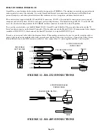
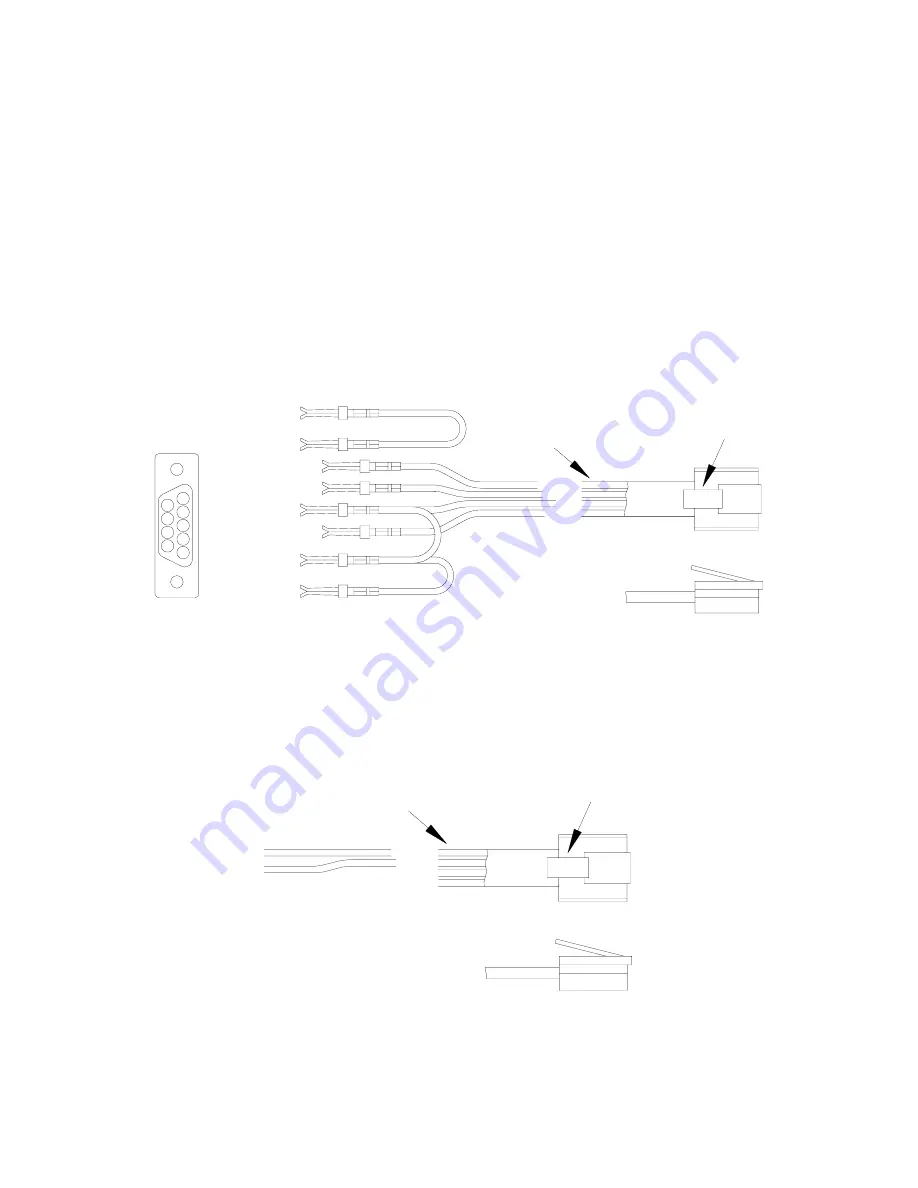
To make you own serial cable, follow the diagrams below. When making connections, be sure to correctly orient the cable as
shown (with the tab on the modular cable facing up, make sure that the Yellow wire is at the top). Connect the Yellow, Green,
Red, and Black wires to the DB-9 connector as shown. Also, connect Pins 1, 4, and 6 together and Pins 7 and 8 together.
6 DSR
BOTTOM VIEW
DB9-FEMALE
5 GND
2 RX
3 TX
1 DCD
4 DTR
9
8
7
6
8 CTS
7 RTS
2
4
5
3
1
YELLOW
GREEN
RED
BLACK
SIDE
TOP
4 POSITION MODULAR
PHONE CABLE
- YELLOW WIRE ON TOP -
- TAB UP -
FIGURE 11 - RS-232 CONNECTIONS
YELLOW
GREEN
A
B
TOP
SIDE
- YELLOW WIRE ON TOP -
4 POSITION MODULAR
PHONE CABLE
- TAB UP -
FIGURE 12 - RS-485 CONNECTIONS


