REMOTE SYSTEM WIRING DIAGRAMS
HAI AUTOMATION SYSTEMS
The thermostat can be connected to an HAI automation system. The
controller can send commands to the thermostat to change mode, cool
setting, heat setting, status of fan and hold, and other items.
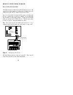
Run a 3 (or 4) conductor wire from the HAI system to the thermostat
location. All thermostats on an Omni, OmniPro, or Aegis controller
are connected to Zone 16 and Output 8. Connect the red COMM
cable wire with the black COMM cable wire. Make the connections
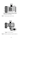
(as shown in Figure 9) using the supplied wire splices.
Note: Do not connect the red COMM cable wire to 12V. If a 4
conductor wire is used, disconnect the red conductor. It is not used!
Figure 9
-
Hookup to an HAI system
Additional thermostats are connected in parallel. They may be
connected in home-run or daisy chain configuration.
GRN
RED
BRN
GRY
COMM
BLACK
RED
BLACK
GREEN
YELLOW
RC-81
THERMOSTAT
OMNI
CONTROLLER
3 OR 4 CONDUCTOR
WIRE. IF PRESENT,
RED WIRE NOT USED.
17


