background image

Chapter Three: Basic System Operation

3.1: Front Panel Layout 

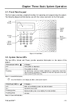
The front panel provides a detailed interface for operating and programming the system. 
The following diagram will familiarize you with the various elements on the front panel.

LCD

Display 

System 
Status
LEDs

Arming

Keys 

Menu
Navigation 
Keys 

Alpha-

numeric

Keypad 

Figure 3.1: Front Panel 

3.2: System Status LEDs 

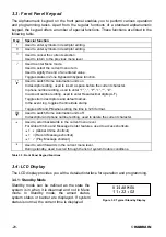
The two LEDs, Armed and Power, provide essential information on the status of the 
system. 

If the Armed LED is…

±

It means… 

Off

The system is disarmed. 

On

The system is armed. 

Flashing

An alarm has occurred. Alarm indication is cleared the next time 
that an arming sequence is initiated or after the relevant event has 
been viewed in the event log.  

Table 3.1: Armed LED Indication 

1

Alarm indication is not displayed after a silent panic alarm.

If the Power LED is… 

a

It means… 

Off

Both AC and Battery power are disconnected.  

On 

System Power is OK. 

Flashing (slow) 

Backup battery low or low battery from transmitters. 

Flashing (fast) 

AC loss. 

Table 3.2: Power LED Indication  

ProGuard800™

  -19- 

Summary of Contents for PROGUARD 800 Series

Page 1: ...PROGUARD 800 PROGUARD 800 SERIES INSTALLATION MANUAL NETHERLANDS 20205 20100607 PROGUARD800TM ALL RIGHTS RESERVED HAIBRAIN...

Page 2: ...or purposes other than specified Haibrain does not accept responsibility for additional damage other than covered by the legal product responsibility This product is not a toy Keep out of reach of chi...

Page 3: ...m Activation 26 Chapter Four Advanced System Operation 28 4 1 Menu Navigation 28 4 2 Stop Communications 28 4 3 Sensor Bypassing Unbypassing 29 4 4 User Codes 29 4 5 Follow Me 31 4 6 Event Log 31 4 7...

Page 4: ...Monitoring station Reporting 66 10 2 General Options for Monitoring station Reporting 67 10 3 Vocal Message Dialler 68 10 4 Remote Programming 70 10 5 Service Call 72 10 6 Communications Options 72 10...

Page 5: ...Transmitter Specifications 106 Appendix C Event Table 107 Appendix D Zone Types 109 Declaration of Conformity 111 ProGuard800 5...

Page 6: ...this manual the following conventions are used This Means Select Use the arrow keys to scroll through the options and press 3 From the Event Log Menu select Clear Log Enter the main menu by pressing 3...

Page 7: ...Pack 7 2V 1 5Ah 6 x 1 2V Ni MH rechargeable cells size AA Fuse Ratings 63mA 250V AC protection fuse 1A 250V battery protection fuse PGM Relay Output Contact Rating 100mA max load Built in Siren 105dB...

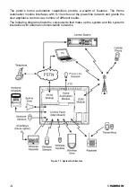
Page 8: ...nterfaces with X 10 units over the powerline network and grants the user appliance control via a number of different media The following diagram shows the components that make up the system and the sy...

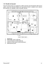
Page 9: ...m Apart from the Main Board each peripheral module is available as an optional extra designed for installation inside the plastic housing Figure 1 2 System Layout 1 Main Board 2 PSTN dialer module opt...

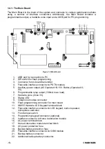
Page 10: ...Battery Operated 6 8V 6 Programmable relay output 100mA max load 7 Hardwire zone Zone 33 8 Status LED 9 Interphone module connector 10 Flash programming connector for main board 11 HK855 Hardwire LCD...

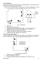
Page 11: ...e terminal block Terminals 1 2 Incoming line from telephone company Terminals 3 4 Outgoing line to telephone 4 Flat cable interface connector to Main Board 5 Telephone socket for incoming line from te...

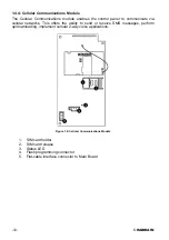
Page 12: ...llular networks This offers the ability to send or receive SMS messages perform up downloading implement cellular 2 way voice applications Figure 1 6 Cellular Communications Module 1 SIM card holder 2...

Page 13: ...dule the control panel should be mounted in a position where the GSM signal is strong x Refer to the following section in order to choose the optimal location for wireless devices in relation to the c...

Page 14: ...he front cover 2 Using a screwdriver carefully press the release tabs as shown in Figure 2 4 3 Lift the front cover away from the back of the housing You will notice that the front cover is attached t...

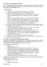
Page 15: ...isplayed on the control panel s LCD press 3 The display automatically switches to the next option for that device For example pressing 3 to confirm Zone registration automatically moves you to the Zon...

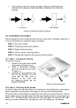
Page 16: ...the Main board to the front panel keypad and remove the Main board Figure 2 5 shows the control panel with the Main board and the battery pack removed Upper Mounting Hole Upper Mounting Hole Location...

Page 17: ...anel perform the Find Modules function see 12 5 Find Modules 2 3 Back Tamper The back tamper switch is an optional feature that provides an extra safeguard in the event that the control panel is remov...

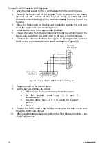
Page 18: ...ugh the wiring hole on the back cover and attach the back cover to the wall using four screws 6 Connect the terminal block on the keypad to the appropriate terminal block on the control panel s main b...

Page 19: ...formation on the status of the system If the Armed LED is It means Off The system is disarmed On The system is armed Flashing An alarm has occurred Alarm indication is cleared the next time that an ar...

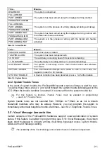
Page 20: ...imal digits A F Toggles item descriptors and default names In the event log toggles the time date stamp Toggles AM and PM when setting the time in 12hr format Used to switch Home Automation units off...

Page 21: ...SYSTEM TROUBLE A trouble condition has been detected press for further details Table 3 5 System Status 3 4 2 System Trouble Tones In the event of system trouble the ProGuard800 sounds a series of tone...

Page 22: ...ed to select the current menu item Used to signify the end of an entered value Toggles status in Zone Bypass Unbypass function FULL Used to arm the system fully In descriptor editing used to insert a...

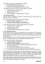
Page 23: ...ming mode has a separate exit and entry delay The arming functions are only available while the system is in Standby mode 3 7 1 Arming Keys The Arming keys enable you to arm the system using any of th...

Page 24: ...ll or Part arming It is not important which arming mode you choose first You can activate the second arming mode during the exit delay of the first arming mode If the first exit delay expires you cann...

Page 25: ...d 4 Press 3 the exit delay for the current arming period is cancelled 3 7 8 Disarming When a sensor is tripped the entry delay counts down each arming method has its own entry delay To disarm the syst...

Page 26: ...E D M A R K 3 9 Remote Arming Disarming via DTMF Using the Telecontrol feature you can fully arm and disarm the system via the telephone with DTMF commands For further information on the Telecontrol...

Page 27: ...Figure 3 8 Fire Alarm Activation To activate a Medical alarm from the front panel or HK855 Hardwire LCD Keypad x Press keys 4 and 6 simultaneously Figure 3 9 Medical Alarm Activation ProGuard800 27...

Page 28: ...m is displayed 3 Press until 7 Service is displayed 4 Press 3 to enter the Service menu 5 Press until 5 Interface Test is displayed 6 Press 3 to choose the displayed function As an alternative to scro...

Page 29: ...he Master code you can edit all other user codes except the Installer code the Guard code and the Monitoring station TWA Code Additionally the Master code grants access to the Event Log the Service me...

Page 30: ...able in the current firmware Code 32 Installer Code The Installer code grants access to the Programming menu and the Service menu Additionally this code enables you to view and clear the Event Log 1 T...

Page 31: ...the capability to receive SMS messages 1 You may only access Follow Me programming if the protocol for Account 3 is programmed as SMS or TWA Follow Me 4 6 Event Log The event log records the last 256...

Page 32: ...o clear the event log 1 From the Event Log menu select Clear Log 62 the OK confirmation message is displayed 2 Press 3 the log is cleared 1 For certain versions of the ProGuard800 software the Clear L...

Page 33: ...3 OK is displayed 2 Press 3 the message is deleted 1 The Record and Play options can also be accessed via a convenient shortcut without needing to enter a valid user code To access the Record Message...

Page 34: ...st displays the following information for each transmitter X ZONE 2 S 6 OK x The zone device number or descriptor Press the key to toggle the display Y Z Descriptor X x The signal strength of the last...

Page 35: ...ing table Press To 1 Increase microphone sensitivity 4 Reduce microphone sensitivity 3 Increase speaker volume 6 Reduce speaker volume Table 4 3 Voice Level Adjustment 4 Press 3 the new settings are s...

Page 36: ...nication may be established 4 7 12 Global Chime The Chime feature causes the control panel s built in siren to ring when specific zones are triggered Using the Global Chime option you can enable or di...

Page 37: ...t with the control panel there are two user codes designed for use with the Telecontrol features The Telecontrol code enables the user to establish communication with the control panel at any time Add...

Page 38: ...k mode press 1 on your telephone To switch back to Listen mode press 0 on your telephone x Press 3 to fully arm the system x Press 4XX to turn HA unit XX ON x Press 5XX to turn HA unit XX OFF x Press...

Page 39: ...k mode press 1 on your telephone To switch back to Listen mode press 0 on your telephone 4 The duration of the call is determined by the TC VM Timeout see 10 6 11 Telecontrol Vocal Message Timeout Ten...

Page 40: ...or presses 7 on their telephone This command restarts the timeout 5 To disconnect before the end of the timeout the operator presses then on their telephone If multiple events are sent the control pan...

Page 41: ...audio channel 1 If you press 9 to answer the call the control panel simultaneously cancels the siren when opening the audio channel 4 If the TWA mode is defined as Simplex see 10 6 12 TWA Mode the au...

Page 42: ...it you want to control 3 Press 3 to select the HA unit 4 Use the arrow keys to toggle the ON OFF command 5 Press 3 to select the command 6 Scroll to the next unit you want to control or press 8 to exi...

Page 43: ...d is executed the system can return a confirmation SMS message to the sender This message includes the HA unit s descriptor and the command that was sent For further information on how to enable this...

Page 44: ...layed 6 4 3 Weekly Schedule To program the days of the week that the schedule is active 1 From the main menu select HA Schedules 8 2 Select an HA unit 3 From the HA unit s sub menu select Schedule 3 4...

Page 45: ...as already been registered at the required location the system will not initiate Registration mode If the device has already been registered at another location attempts to register are ignored by the...

Page 46: ...pervision time between 02 00 and 23 59 hours 7 5 Re Synchronization Transmissions that are out of synchronization are rejected by the system For example it is not possible to arm or disarm the system...

Page 47: ...hods in which the zone is included To program the Arm Set option 1 From the Programming menu select Devices Zones 911 2 Select the sensor you want to program 3 From the zone s sub menu select Arm Set...

Page 48: ...nabled This door must be closed by the end of the Exit delay otherwise an alarm is generated If the magnetic contact s zone is defined as Force Arm disabled the system will not be ready to arm until y...

Page 49: ...rt B2 Perimeter Medical Emergency PR811 KR814 Figure 7 1 Keyfob Button Assignments The following sections explain the programming options exclusive to the KR814 Keyfob transmitter These programming op...

Page 50: ...ation KR814 Using the four button Keyfob you can activate an SOS Panic alarm by pressing two buttons simultaneously Figure 7 2 illustrates how to activate an SOS Panic alarm on the KR814 wireless Keyf...

Page 51: ...the on board transmitter to the wireless siren s receiver 1 Set the wireless siren s receiver to Registration mode refer to the siren s installation instructions for further information 2 Activate the...

Page 52: ...0 00 3 Press 3 when the desired setting is displayed 7 10 4 Wired Siren When the system generates an audible alarm both the wired built in siren and the wireless siren are sounded This option allows y...

Page 53: ...rt 2 or Perimeter 3 3 Enter a delay time 000 255 seconds 4 Press 3 when the desired setting is displayed 8 2 Arm on Exit The Arm on Exit feature cancels the unnecessary remainder of the Exit delay tha...

Page 54: ...y Exit Exit Restart 926 2 Select Enabled or Disabled 3 Press 3 when the desired setting is displayed 8 6 Arming Tones Arming tones are the tones sounded by the control panel s built in siren and or th...

Page 55: ...ine which trouble condition is present from the LCD keypad on the front panel For additional information see 3 4 2 System Trouble Tones 8 8 1 Trouble Tones The Trouble Tones option allows you to enabl...

Page 56: ...ker Volume option determines the volume level of the tones sounded by the speaker To program the Speaker Volume option 1 From the Programming menu select Tones Tones Options Speaker Vol 9392 2 Select...

Page 57: ...ful attempts are made to enter the user code To program the Code Lockout setting 1 From the Programming menu select System Options Code Lockout 9402 2 Select Enabled or Disabled 1 During the 30 minute...

Page 58: ...faulty sensor s zone to allow system arming until the problem is remedied 1 Zone bypassing is valid for one arming period only All bypassed zones are automatically unbypassed when the system is disarm...

Page 59: ...elapse before an AC Loss report is sent to the monitoring station If AC power is restored before the event message is sent the event message is cancelled and will not be sent You can program an AC Lo...

Page 60: ...To edit the Banner text 1 From the Programming menu select System Options Display Banner 94062 2 Edit the Banner text using the alphanumeric keypad 3 Press 3 when you have finished editing 1 The syst...

Page 61: ...cal alarm Burglary Burglary alarm Fire Alarm Fire alarm Any arming method system disarmed or PGM Cut off Zone Status Open zones steady Bypassed zones pulsing All zones closed and no zones bypassed Ent...

Page 62: ...n 3 Press 3 when the desired setting is displayed 9 8 Guard Code for future use The Guard Code is a future option that is not available in the current firmware The default setting for this option is d...

Page 63: ...tions Mic Speaker 9412 2 Select Internal External or Internal External 9 13 Vocal Messages The Vocal Messages option allows you to enable disable vocal annunciation of system status When this feature...

Page 64: ...caused by failure to report press until you have scrolled through the entire system trouble list If the Report Fail Trouble is disabled failure to report an event does not cause a system trouble condi...

Page 65: ...rted at the end of the Verified Fire timeout x An alarm occurs from a Fire zone the alarm is restored and then a second alarm occurs from the same zone during the Verified Fire timeout in this case th...

Page 66: ...mmunications Accounts 951 2 Select a CS account 1 3 3 From the account s sub menu select Account Number 2 4 Enter up to eight digits Enter leading zeros for account numbers of less than eight digits U...

Page 67: ...onitoring station Reporting The options included in this section concern the three accounts used for monitoring station reporting 10 2 1 Call Continue When reporting an event the system attempts to ca...

Page 68: ...eport cycles programmed is 3 Figure 10 1 Typical Report Cycle Sequence 10 3 Vocal Message Dialler The Vocal Message Dialler is a feature that calls the user s telephone number when specific events occ...

Page 69: ...are acknowledged this cycle is repeated twice This means that the control panel performs a maximum of three call attempts to each VM account 10 3 1 Telephone Number To edit a Vocal Message account s t...

Page 70: ...4 Remote Programming Marmitek s ProGuard800 Remote Programmer RP software enables you to operate and program the system from a PC either on site or from a remote location The software provides a comp...

Page 71: ...r or PSTN communication during remote programming For PSTN communication the RP uses a double call method so that the line can be shared with regular telephone handsets an answering machine or fax The...

Page 72: ...STN 10 6 Communications Options 10 6 1 Line Monitor The Line Monitor feature monitors both the PSTN telephone line and the GSM network If a problem is detected with either of these a Media Loss event...

Page 73: ...frequency of automatically calculated periodic test messages To program the Auto Interval 1 From the Programming menu select Communications Comm Options Auto Interval 95404 2 Select Daily Weekly or Mo...

Page 74: ...ontrol panel automatically dials the RP Call back number and connects to the RDM server The time interval between maintenance sessions is called the RDM period To program the RDM period 1 From the Pro...

Page 75: ...ystem also enters the GSM signal strength in the event log 1 If the Periodic Test is disabled the GSM RX Report feature will not function The GSM RX report belongs to the Peripherals event group see 1...

Page 76: ...strength If a problem is detected with the GSM a Media Loss event is registered in the log and sent to the monitoring station after the time defined in the GSM ML Time parameter GSM Media Restore wil...

Page 77: ...nt groups This division allows you to enable or disable reporting or Two Way Audio for a specific group of events The different event groups are as follows x Burglary 1 x Fire 2 x Open Close arm disar...

Page 78: ...This allows you to enable or disable the Vocal Message feature for a specific group of events For further information on this feature see 10 3 Vocal Message The vocal message event groups and their a...

Page 79: ...o Disarm o Disarm after Alarm x Water 8 o Zone Water Alarm Flood To enable disable the vocal message for an event group 1 From the Programming menu select Communications VM Event Opt 956 2 Select an...

Page 80: ...ese X 10 receivers as HA units Each HA unit has two codes that are used for identification These codes are known as the House code and the Unit code and are usually defined by adjusting the dials that...

Page 81: ...ming HA Units 961 2 Select an HA unit 01 16 3 From the HA unit s sub menu select On by Arm 05 4 Select Enabled or Disabled 11 2 4 On by Alarm On by Alarm is a feature designed for use with X 10 sirens...

Page 82: ...ect Randomize 09 4 Select Enabled or Disabled 11 2 8 Pulse Time The Pulse Time determines the manner in which an HA unit responds to the On command You can program each HA unit switch on momentarily T...

Page 83: ...o program the system House code 1 From the Programming menu select HA Programming House Code 962 2 Using the arrow keys select a House code from the options available A P 11 4 HA Control The HA Contro...

Page 84: ...t select the set of programming defaults that you want to load 3 For firmware versions that include multi default and multi language support select the required interface language 4 Press 3 to confirm...

Page 85: ...that are connected to the system bus With this information the system knows which add on modules should be present enabling supervision for those modules To run the Find Modules test 1 From the Progra...

Page 86: ...Appendix A Menu Structure Legend Installer code required Master code required 86 HAIBRAIN...

Page 87: ...ProGuard800 87...

Page 88: ...88 HAIBRAIN...

Page 89: ...ProGuard800 89...

Page 90: ...90 HAIBRAIN...

Page 91: ...ProGuard800 91...

Page 92: ...92 HAIBRAIN...

Page 93: ...bjects in front of the detector x Avoid a location which comes in direct contact with radiators heating cooling ducts mirrors and air conditioners x Select an appropriate installation height from Tabl...

Page 94: ...nstall the Mode jumper only after applying battery power 5 From the Programming menu select Devices Zones 911 6 Select the zone to which you want to register the transmitter the system initiates Regis...

Page 95: ...LED activates and deactivates accordingly Wait five seconds after each detection before continuing the test 4 After completing the walk test remove the jumper and place it over one pin for storage se...

Page 96: ...11 Jumper Position Operation Mode 4 Select the zone to which you want to register the transmitter the system initiates Registration mode When Save appears on the panel s LCD display press 9 Pins 1 2 U...

Page 97: ...rectly aligned with the guideline on the transmitter 1 Do not install the magnet further than 1cm from the transmitter 12 Test the transmitter making certain that the LED is lit when opening the door...

Page 98: ...mode When Save appears on the panel s LCD display press 3 5 After registration press the US832 s tamper switch to terminate Test mode 6 Before permanently mounting the unit test the transmitter from...

Page 99: ...sight of all windows to be protected x If mounting on the wall try to install the sensor directly opposite the protected window If this is not possible adjoining side walls are also a good location x...

Page 100: ...tor Antenna Mounting Knockout Mounting Knockout Acoustic Sensor Figure B 7 GB843 cover off 1 Open the housing using a small flat head screwdriver to separate the base from the cover 2 Remove the insul...

Page 101: ...using the mounting screws provided 10 Write the number of the zone on the sticker provided and affix the sticker inside the front cover for future reference 11 Close the front cover making sure that i...

Page 102: ...separate the cover from the base 3 Install a 9V battery into the detector s battery snap 4 Insert the Test jumper the SD833 enters Test mode and the LED flashes every few seconds 5 From the Programmi...

Page 103: ...battery is low the PR811 s LED flashes during transmission and a Low Battery signal is sent to the receiver When either of these two indications are observed replace the unit Figure B 10 PR811 KR814...

Page 104: ...o register wireless keypads 1 From the Programming menu select Devices Keypads 913 2 Select the keypad you want to register the system initiates Registration mode 3 Press a button on the keypad making...

Page 105: ...r located at the rear of the unit To do so press the release tab using a small screwdriver and lift the cover away from the RC840 s plastic housing 2 Observing correct polarity replace the battery 9V...

Page 106: ...n 20 A standby RFI Immunity 40V m Power 9V Alkaline Battery RFI Immunity 40V m Ambient temperature 0 C to 60 C operation Dimensions 138 x 118 x 44mm GB843 Antenna Built in Whip Power 3 6V AA Lithium B...

Page 107: ...Device Number Environmental Alarm NUA 1150 Device Number Environmental Alarm Restore NUH 3150 Device Number Alarm Cancel NOC 1406 User Number Fire Fire Alarm NFA 1110 Device Number Fire Alarm Restore...

Page 108: ...l 0 9 Zone Trouble NBT 1380 Device Number Zone Trouble Restore NBJ 3380 Device Number RF Jamming FM Jamming NXQ 1344 Device Number FM Jamming Restore NXH 3344 Device Number Medical Medical Alarm NMA 1...

Page 109: ...the area crossed in order to reach the keypad Event Group Burglary Panic Panic zones are always active When a Panic zone is triggered a Panic alarm is generated This zone type is designed for panic bu...

Page 110: ...active When triggered these zones generate an Environmental alarm These zones are designed for applications that monitor environmental conditions such as temperature or humidity If the Bell option is...

Page 111: ...its packaging must not be disposed of with unsorted municipal waste The symbol indicates that this product should be disposed of separately from regular household waste streams It is your responsibili...

Page 112: ......

Reviews: