background image

5

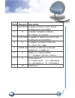
For notebook PC use:

HI-204

III

-USB connect with a LaptopPC USB port.

USB port

Summary of Contents for HI-204III

Page 1: ...HI 204III USB Ultra High Sensitive USB GPS Receiver...

Page 2: ...SB DRIVER FILES B WINDOWS 98 INTERFACE 1 Install GPS USB Driver 2 Check Enable COM Port Number 3 Remove GPS USB Driver C WINDOWS XP INTERFACE 1 Install GPS USB Driver 2 Check Enable COM Port Number 3...

Page 3: ...1 HI 204III USB WATERPROOF Ultra High Sensitive USB GPS Receiver...

Page 4: ...g the receiver you can determine your location with great precision The satellites are positioned so that we can receive signals from six of them nearly 100 percent of the time at any point on Earth Y...

Page 5: ...ictions on who can use the signal available to civilians GPS technology can be used in a variety of fields besides providing navigation for vehicles on the sea in the air and on the ground GPS applica...

Page 6: ...cations for car navigation personal navigation or touring devices tracking and marine navigation purpose Users can simply plug it into a LaptopPC running with suitable mapping and routing software for...

Page 7: ...5 For notebook PC use HI 204III USB connect with a LaptopPC USB port USB port...

Page 8: ...st and maximum flexibility suitable for a wide range of OEM configurations including handhelds sensors asset tracking PDA centric personal navigation system and vehicle navigation products Its 20 para...

Page 9: ...7 1 2 Features 20 parallel channel GPS receiver 4000 simultaneous time frequency search bins SBAS WAAS EGNOS support 159dBm tracking sensitivity 8 second hot start 40 second cold start...

Page 10: ...id position velocity and time information are transmitted through the on board serial interface The receiver uses the latest stored position satellite data and current RTC time to achieve rapid GPS si...

Page 11: ...navigation when four or more satellites are tracked When three or fewer satellites are tracked altitude hold is enabled using the last computed altitude and 2D navigation mode is entered With signal...

Page 12: ...input Power consumption Supply Current Backup power 43mm L x 42mm W x 13mm H 23g Description SiRF StarIII technology L1 1575 42 MHz 1 023 MHz chip rate 20 10 meters 2D RMS 5 meters 2D RMS WAAS correc...

Page 13: ...11 2 2 LED INDICATOR LED flashing 0 25Hz LED flashing 1Hz Signal Searching Position Fixed...

Page 14: ...ECTION 3 HARDWARE INTERFACE 3 1 MECHANICAL DIMENSIONS 73 0 2 I O Cable I O Cable I O Cable Build in patch antenna LED indicator Magnetic CPU Top View Lateral View Bottom View 69 0 2 20 0 2 69 0 2 Unit...

Page 15: ...s generated when the GPS receiver is powered on Proper adjustment of the 1PPS output to align with the GPS second requires calculation of the receiver clock offset and clock drift rate as part of the...

Page 16: ...valid position fix the 1PPS output will drift away from the GPS second and the 1PPS Valid Signal will become inactive Upon re acquiring enough satellites to generate consecutive valid position fixes...

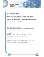
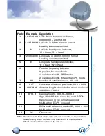
Page 17: ...for commands and data to be successfully transmitted and received The default receiver protocol is 4800 bps 8 data bits 1 stop bit and none parity 4 1 NMEA OUTPUT MESSAGE SPECIFICATION The HI 204III U...

Page 18: ...This standard is fully define in NMEA 0183 Version 3 01 The standard may be obtained from NMEA www nmea org 4 1 2 GGA GPS FIX DATA Time position and position fix related data number of satellites in u...

Page 19: ...cator 0 position fix unavailable 1 valid position fix SPS mode 2 valid position fix differential GPS mode Number of satellites in use 00 12 Horizontal dilution of precision 00 0 99 9 Antenna height ab...

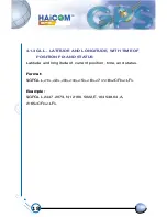
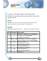
Page 20: ...ATITUDE AND LONGITUDE WITH TIME OF POSITION FIX AND STATUS Latitude and longitude of current position time and status Format GPGLL 1 2 3 4 5 6 7 8 CR LF Example GPGLL 2447 2073 N 12100 5022 E 104548 0...

Page 21: ...itted Latitude hemisphere indicator N North S South Longitude in dddmm mmmm format Leading zeros transmitted Longitude hemisphere indicator E East W West UTC time in hhmmss ss format 000000 00 235959...

Page 22: ...6 21 09 17 10 8 02 1 10 6 07 CR LF Field 1 2 3 4 5 6 7 Example A 3 26 21 09 17 10 8 02 1 10 6 07 Description Mode M Manual A Automatic Fix type 1 not available 2 2D fix 3 3D fix PRN number 01 to 32 of...

Page 23: ...four satellite details are transmitted per message Additional satellite in view information is sent in subsequent GSV messages Format GPGSV 1 2 3 4 5 6 7 4 5 6 7 8 CR LF Example GPGSV 2 1 08 26 50 01...

Page 24: ...f GSV messages to be transmitted Number of current GSV message Total number of satellites in view 00 12 Satellite PRN number GPS 01 32 SBAS 33 64 33 PRN120 Satellite elevation number 00 90 degrees Sat...

Page 25: ...ANDED MINIMUM SPECIFIC GPS TRANSIT DATA Time date position course and speed data Format GPRMC 1 2 3 4 5 6 7 8 9 10 11 12 13 CR LF Example GPRMC 104549 04 A 2447 2038 N 12100 4990 E 016 0 221 0 250304...

Page 26: ...ormat Leading zeros transmitted Latitude hemisphere indicator N North S South Longitude in dddmm mmmm format Leading zeros transmitted Longitude hemisphere indicator E East W West Speed over ground 00...

Page 27: ...221 0 T 224 3 M 016 0 N 0029 6 K A 1F CR LF Field 1 2 3 4 5 6 Example 221 0 224 3 016 0 0029 6 A 1F Description True course over ground 000 0 359 9 degrees Magnetic course over ground 000 0 359 9 deg...

Page 28: ...the receiver The new settings will remain effective on next power on as long as the on board rechargeable backup battery is not discharged After the backup battery is discharged factory preset default...

Page 29: ...n s open COM port The PS II connector did not insert correctly or some other application is the COM port Plug HI 204III USB connector firmly or close all other application that occupied the COM port C...

Page 30: ...28 USB Driver Setup Guide HI 204III USB USB GPS Receiver...

Page 31: ...xecution file removes GPS USB driver from the PC Type Setup Information This file provides major setup information Type System File This file provides Windows 2000 and Windows XP hardware specific int...

Page 32: ...30 Figure 1 Screen of GPS USB Driver Group Figure 2 Screen of GPS USB Driver Win 2000 and Win XP System File...

Page 33: ...31 Figure 3 Screen of GPS USB Driver Win 98 and Win ME Group...

Page 34: ...on of GPS USB driver there are three procedures required The first thing is to turn on PC in the Windows environment The second thing is to copy USB driver into HDD The third thing is to plug the GPS...

Page 35: ...33 Step 1 Click the Next button Figure 4 Win 98 Automatic Installation Driver Screen...

Page 36: ...34 Step 2 Select Automatically and click the Next button Figure 5 Win 98 Automatic Installation Driver Screen...

Page 37: ...35 Step 3 Specific driver location and click the Next button Figure 6 Win 98 Automatic Installation Driver Screen...

Page 38: ...36 Step 4 Click the Next button Figure 7 Win 98 Automatic Installation Driver Screen...

Page 39: ...37 Step 5 Click the Finish button Figure 8 Win 98 Automatic Installation Driver Screen...

Page 40: ...ng map or chart software Please notice that this remark is very important if not configured properly the mapping software will not communicate with the GPS receiver To check your assigned COM port for...

Page 41: ...39 Step 2 Double click the Control Panel icon Figure 10 My Computer Screen...

Page 42: ...40 Step 3 Double click the System icon Figure 11 Control Panel Screen...

Page 43: ...41 Step 4 Press Device Manager button Figure 12 System Properties Screen...

Page 44: ...42 Step 5 Slect USB to Serial Port COM3 and click Propertes button Figure 13 System Properties Screen...

Page 45: ...43 Step 6 Browse COM3 properties Figure 14 System Properties Screen...

Page 46: ...er and install new one Step 1 Remove GPS USB driver by double clicking the icon show in Figure 15 A dialog window shown in Figure 16 will be pop up Figure 15 GPS USB Driver Remove Icon Step 2 Click OK...

Page 47: ...e first thing is to turn on PC in the Windows environment The second thing is to copy USB driver into HDD The third thing is to plug the GPS receiver into the USB port of PC and then follow the instal...

Page 48: ...ude this location in the search OR Browse to specific GPS USB driver location Figure 19 Win XP Automatic Installation Driver Screen Step 3 Click Continue Anyway button Figure 20 Win XP Automatic Insta...

Page 49: ...47 Step 4 Finish screen Figure 21 Win XP Automatic Installation Driver Screen Step 3 Click Continue Anyway button Figure 22 Win XP Automatic Installation Driver Screen...

Page 50: ...he GPS receiver when configuring map or chart software Please notice that this remark is very important if not confingured properly the mapping software will not communicate with the GPS receiver TO c...

Page 51: ...49 Step 2 Select Hardware Figure 23 System Properties Screen...

Page 52: ...50 Step 3 Select Device Manager Figure 24 System Properties Screen...

Page 53: ...51 Step 4 Select Ports COM LPT Figure 25 Device Manager Screen...

Page 54: ...52 Step 5 Select COM4 Figure 26 Device Manager Screen...

Page 55: ...53 Step 6 Select Driver Figure 27 USB to Serial Bridge Screen...

Page 56: ...54 Step 7 Browse COM4 properties Figure 28 USB to Serial Bridge Properties Screen...

Page 57: ...and install new one Step 1 Remove GPS USB driver by double clicking the icon show in Figure 29 A dialog window shown in Figure 30 will be pop up Figure 29 GPS USB Driver remove icon Step 2 Click OK bu...

Page 58: ...56 D Change COM Port Number Application Program If the notebook assigns COM number to COM5 then can to execute SetCOM exe for COM number change...

Page 59: ...gn by double clicking the icon show in Figure 32 and then small icon shown in Figure 34 will be pop up Figure 32 SetCOM exe Icon Figure 33 Start bar on the right below corner of screen Figure 34 Start...

Page 60: ...58 Step 2 by clicking the icon show in Figure 34 a dialog window shown in Figure 35 will be pop up Figure 35 COM port number change screec...

Page 61: ...59 Step 3 for example change COM3 become COM4 first Click COM3 and COM4 then Click Set button Figure 36 COM port number change screec Step 4 Click Yes button Figure 37 Notification Screen...

Page 62: ...oesn t work please try to unplug the GPS receiver from the USB port wait for 5 8 seconds and re plug the GPS receiver into your PC 3 Occasionally the mouse cursor does not work properly when you run t...

Page 63: ...ions below Click start click Control Panel double click system icon click Hardware click Device Manager click Mouse select the wrong mouse click your real mouse right button disable the wrong mouse Sh...

Page 64: ...WATERPROOF USB GPS Receiver...

Reviews: