background image


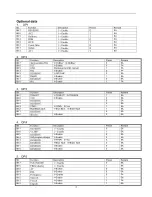
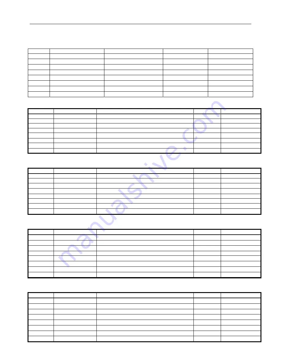
Optional data 

1.  OP1 

Bit Function 

Description 

Preset 

Remark 

Bit 7 

RESERVE


1 = Enable


EA


Bit 6 

AV2


1 = Enable


EA


Bit 5 

Halftone


1 = Enable


EA


Bit 4 

RGB


1 = Enable


EA


Bit 3 

DVD 


1 = Enable


EA


Bit 2 

Comb filter


1 = Enable


EA


Bit 1 

SVHS


1 = Enable


EA


Bit 0 

AV1 


1 = Enable


EA


2. OP2 

Bit Function 

Description 

Preset 

Remark 

Bit 7 

Ident sensitive PAL 

1=21dBµV  0=26dBµV 

EA 

Bit 6 

TILT 

1=Enable 

EA 

Bit 5 

OSO 

Translucence OSD manual 

EA 

Bit 4 

FSL 

1=Enable   

EA 

Bit 3 

RESERVE


1=QD 0=HF 

EA 

Bit 2 

FMWS 

1=Enable 

EA 

Bit 1 

RESERVE


1=Enable 0 

EA 

Bit 0 

AVL 

1=Enable 

EA 


3. OP3 

Bit Function 

Description 

Preset 

Remark 

Bit 7 

TDA8377 

1=TDA9377  0=TDA9378 

EA 

Bit 6 

16:9 

1=Enable 

EA 

Bit 5 

RESERVE


 0 

EA 

Bit 4 

RESERVE


 0 

EA 

Bit 3 

YPbPr 

1=YPbPr  0=Yuv 

EA 

Bit 2 

Blue/Black back 

1=Blue Back    0=Black Back 

EA 

Bit 1 

RESERVE


 0 

EA 

Bit 0 

Woofer


1=Enable 0 

EA 


4. OP4 

Bit Function 

Description 

Preset 

Remark 

Bit 7 

RESERVE


1 = Enable


0 EA 

Bit 6 

VCHIP


1 = Enable


1 EA 

Bit 5 

RESERVE


1=Enable 0 

EA 

Bit 4 

Soft program change 

1=Enable 

EA 

Bit 3 

RESERVE


1=YPbPr  0=Yuv 

EA 

Bit 2 

RESERVE


1=Blue Back  0=Black Back 

EA 

Bit 1 

RESERVE


1=Enable 0 

EA 

Bit 0 

RESERVE


1=Enable 0 

EA 


5. OP5 


7

Bit Function 

Description 

Preset 

Remark 

Bit 7 

Auto character   

1 = Enable


0 EA 

Bit 6 

FREQ display


1 = Enable


1 EA 

Bit 5 

AV


1=Enable 0 

EA 

Bit 4 

PAL


1=Enable 0 

EA 

Bit 3 

Portuguese


1= Enable 

EA 

Bit 2 

Spanish 


1=Enable 1 

EA 

Bit 1 

French


1=Enable  

EA 

Bit 0 

English


1=Enable 1 

EA 
Summary of Contents for BH2004D

Page 1: ...D COLOUR TELEVISION Service Manual MODEL BH2004D America Features 51cm super flat picture tube Auto search 181 program presetting and memory CCD V CHIP Haier Group Edition 2004 4 17 NO M MR AE BH2004D...

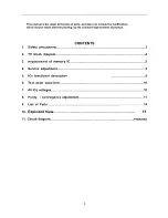
Page 2: ...y the constant improvement of product CONTENTS 1 Safety precautions 3 2 TV block diagram 4 3 Replacement of memory IC 5 4 Service adjustment 5 5 ICs functional description 8 6 Test point waveform 10 7...

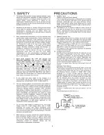
Page 3: ...t check high voltage by drawing an arc Use a high voltage meter or a high voltage probe with a VTVM Discharge the picture tube before attempting meter connection by connecting a clip lead to the groun...

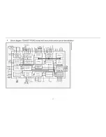
Page 4: ...2 Block diagram TDA8377 PS N2 series with mono intercarrier sound demodulator 4...

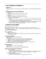
Page 5: ...stment of corresponding factory menus Press EXIT key to exit factory mode Focus adjustment 1 Receive a crosshatch signal 2 While watching the screen adjust the FOCUS VR on the FBT to make the vertical...

Page 6: ...4A 18 AVLT TDA9874A AVL delay time 0 OFF 1 2s 2 4s 3 8s 1 9860 Sub volume of TDA9860 59 59 IFFS IF 2 38 9MHz 3 38MHz 2 HDOL Cathode drive level 5 AGC IF AGC speed 1 VG2B VG2 Brightness 42 5 Picture pr...

Page 7: ...t 7 TDA8377 1 TDA9377 0 TDA9378 1 EA Bit 6 16 9 1 Enable 0 EA Bit 5 RESERVE 0 EA Bit 4 RESERVE 0 EA Bit 3 YPbPr 1 YPbPr 0 Yuv 1 EA Bit 2 Blue Black back 1 Blue Back 0 Black Back 1 EA Bit 1 RESERVE 0 E...

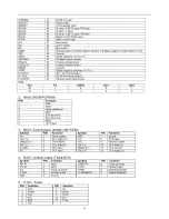
Page 8: ...f digital ground of TV processor SECPLL 13 Internally connected VP2 14 2 nd supply voltage TV processor 8V DECDIG 15 decoupling digital supply of TV processor PH2LF 16 Phase 2 filter PH1LF 17 Phase 1...

Page 9: ...control signal input Note Pin TV SVHS AV1 AV2 62 1 0 0 1 63 1 1 0 0 2 N902 24C08 PCF8598 PIN Function 1 GND 2 GND 3 Upper resistance 4 GND 5 SDA data wire 6 SCL clock wire 7 GND 8 5V Power 3 N601 Soun...

Page 10: ...4 4 5 1 1 8 0 0 18 0 17 0 2 3 8 5 3 PIN 17 18 19 20 21 22 23 24 25 26 27 28 29 30 31 32 V 4 0 4 0 5 0 7 0 8 1 9 1 9 3 9 3 8 1 6 3 2 2 3 0 2 3 0 2 PIN 33 34 35 36 37 38 39 40 41 42 43 44 45 46 47 48 V...

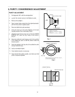
Page 11: ...e centre of the screen Fig 3 8 Move the deflection yoke forward and fix the position of the deflection yoke so that the whole screen will become green 9 Insert the wedge to the top side of the deflect...

Page 12: ...nvergence DYNAMIC CONVERGENCE ADJUSTMENT 1 Move the deflection yoke up and down and overlap lines in the periphery Fig 2 2 Move the deflection yoke left to right and overlap the lines in the periphery...

Page 13: ...106 25V 220 F C102 MTZJ5 1B DZ102 63V 0 1 F C101 1 6W 68K R261 1N4148 VD217 1 6W 9 1K R260 1 6W 1K R227 1 6W 9 1K R262 B4 12V C214 104 SYSTEM 1W 33 R110 LGA0203 100 L102 SDA SCL 1 6W 22 R103 SPEAKER S...

Page 14: ...group Sincere Forever 28...

Reviews: