background image

INSTALLATION

PAGE 33

ENGLISH

SE

C

TION E

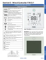
NOTE: The display backlight must be illumi-
nated before proceeding. To turn the back-
light on, press any key (MODE, FAN, 

pq

TIME, or SET) located at the bottom of the 
display, or press the ON/OFF key located at 
the top of the display.
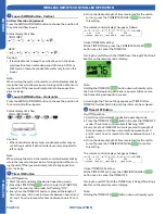
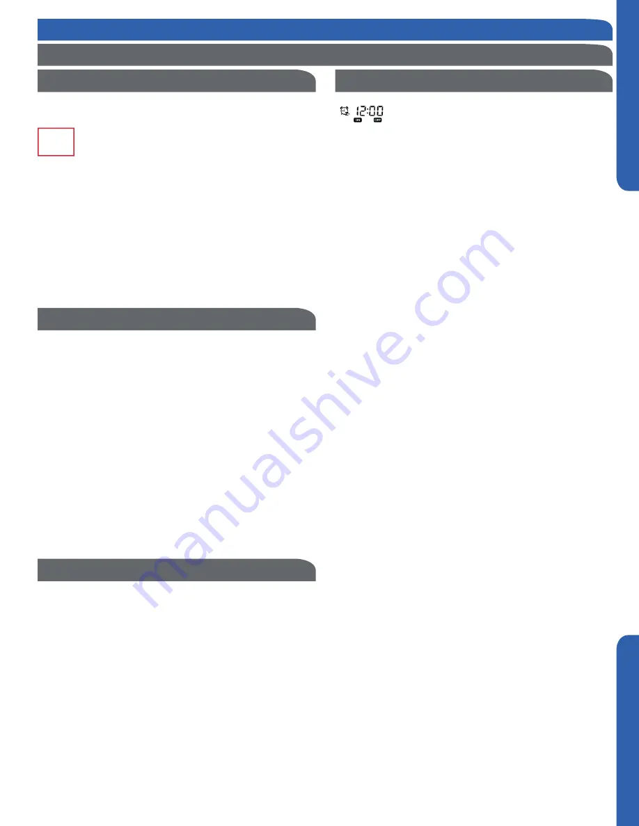
 
Timer ON
Press the TIMER key once, the ON timer icon will appear in the 
upper right corner of the screen. The ON icon and hour posi-

tion are flashing. Press the 

pq

 keys to set the hour.  Press 

the TIMER key again, the ON icon and minutes position are 

now flashing. Press the 

pq

 keys to set the minutes. Press the 

SET key to confirm the setting. 

Timer OFF
Press the TIMER key 3 times, the OFF timer icon will appear in 
the upper right corner of the screen. The OFF icon and hour 

position are flashing. Press the 

pq

 keys to set the hour.  

Press the TIMER key again, the OFF icon and minutes position 

are now flashing. Press the 

pq

 keys to set the minutes. Press 

the SET key to confirm the setting.

Timer ON/OFF
Press the TIMER key 5 times, the ON/OFF timer icon will ap-
pear in the upper right corner of the screen. The ON icon and 

hour position are flashing. Press the 

pq

 keys to set the hour.  

Press the TIMER key again, the ON icon and minutes position 

are now flashing. Press the 

pq

 keys to set the minutes. Press 

the TIMER key again, the OFF icon and hour position are now 

flashing. Press the 

pq

 keys to set the hour. Press the TIMER 

key again, the OFF icon and minutes position are now flashing. 

Press the 

pq

 keys to set the minutes. Press the SET key to 

confirm the setting. Based on the times set, the indoor unit 
will determine which event happens first (ON-OFF or OFF-
ON) and adjusts the arrow direction accordingly. 

If neither 

pq

 key is pressed within 10 seconds, or if the 

MODE, FAN, or ON/OFF keys are pressed prior to pressing the 
SET key, the setting function is canceled and reverts back to 
the previous setting.

Timer Cancel
Press the TIME key up to 9 times to cycle through the timer 
settings. When the timer icon disappears, the timer function is 
canceled.

Note:  An active timer function will remain displayed on screen 
until the set time has been reached and command completed. 

Timer Function Setting

WIRED CONTROLLER OPERATION

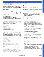
Settings & Functions

Press the SET key. The swing louver function icon will 
be displayed. Press the 

pq

 keys to advance through 

the functions to select ECO function. (The icon will 

be flashing) Press the SET key to confirm the setting. The ECO 

icon will remain on.

To cancel ECO function, repeat the above steps.

NOTE: The energy saving default parameters are listed below:
74°F Lowest temperature limit of Cooling and Dry mode.
78°F Highest temperature limit of Heating mode.

74°F – 86°F Temperature adjustment range in Cooling and Dry 

mode. 

60°F – 78°F Temperature adjustment range in Heating mode.

ECO

For Cooling
Under Cooling mode, set the temperature to 86°F. Press and 
hold the FAN key for 5 seconds. The Cooling ECO param-

eter (flashing) will be displayed in the upper left corner of the 

screen. Default temperature is 74°F. Press the 

pq

 keys to 

adjust the lowest target cooling temperature. Press the SET 
key to confirm the setting and exit setup. 

For Heating
Under Heating mode, set the temperature to 60°F. Press and 
hold the FAN key for 5 seconds. The Heating ECO parameter 

(flashing) will be displayed in the upper right corner of the 

screen. Default temperature is 78°F. Press the 

pq

 keys to 

adjust the highest target heating temperature. Press the SET 
key to confirm the setting and exit setup. 

Press and hold the SET and FAN keys for 5 seconds. The cur-
rent static pressure will be displayed in the upper right corner 

of the screen and the “Static Pressure” icon will begin to flash. 

Press the TIME key to shift the unit no. displayed in the upper 
left corner of the screen. The unit numbers are from 00-15.
Press the 

pq

 keys to change the static pressure grade, 

shown in the upper right corner of the screen.

Number range is 01-04. Press the SET key to confirm the 

setting.  Press the MODE, FAN, or ON/OFF key to exit the 
function. If no key is pressed in 10 seconds, the function will 
also exit. 

NOTE:  This function requires the  ON/OFF key LED to be 
turned ON and the screen backlight to be illuminated. 

NOTE:  This function requires the  ON/OFF key LED to be 
turned ON and the screen backlight to be illuminated. 

NOTE:  This function requires the  ON/OFF key LED to be 
turned ON and the screen backlight to be illuminated. 

ECO Energy Saving Function

ECO Parameter Setting

Static Pressure Grade Inquiry & Adjustment

Summary of Contents for 1U12LC2VHA

Page 1: ...Section B Indoor Unit Installation Wall Mount 13 Section C Indoor Unit Installation Cassette 17 Section D Indoor Unit Installation Slim Duct 23 Section E Wired Controller YR E17 29 Section F Wireless Remote Cotroller 37 Table of Cont ents AW12LC2VH AW18LC2VH AD12SL2VH AD18SL2VH AB12SC2VH AB18SC2VH 1U12LC2VHA 1U18LC2VHA 0010586610 ...

Page 2: ...im Duct Type Indoor M Mid Static Duct Type Indoor H High Static Duct Type Indoor W Wall Mount Type Indoor 1 Single Zone Outdoor 2 Two Zone Outdoor 3 Three Zone Outdoor 4 Four Zone Outdoor M Mid Static Duct Type Indoor H High Static Duct Type Indoor Nominal Capacity In Btu hr x 1000 Product Family MS LC SL SC Voltage 1 115V 2 230V Compressor Speed V Variable Speed System Type H Heat Pump C Cool Onl...

Page 3: ...00 3 94 8 45 5 43 Dimension Height in mm 11 280 12 3 4 322 7 5 16 185 7 5 16 185 10 1 4 260 10 1 4 260 Dimension Width in mm 33 5 8 855 39 1 4 997 33 7 16 850 46 1 16 1170 22 7 16 570 22 7 16 570 Dimension Depth in mm 8 1 16 204 9 1 4 235 16 9 16 420 16 9 16 420 22 7 16 570 22 7 16 570 Max Ex ternal Static Pressure in W G Pa NA NA 0 16 40 0 16 Pa NA NA Drainpipe Size O D in NA NA 1 1 4 1 1 4 1 1 4...

Page 4: ...ore conducting repair work A charged capacitor can cause electrical shock Be sure to use parts listed in the service parts of the applicable model and appropriate tools to conduct repair work Never attempt to modify the equipment The use of inappropriate parts or tools can cause electrical shock excessive heat generation or fire When relocating the equipment make sure that the new installation sit...

Page 5: ...ombustible gas leaks and remains near the unit it may cause a fire Be sure to install the packing and seal on the installation frame correctly If the packing and seal are not properly installed water can spill out wetting furniture and the floor Replace power cables and lead wires if they are scratched or deteriorated Damaged cable and wires can cause electrical shock excessive heat generation or ...

Page 6: ... This page intentionally left blank ...

Page 7: ...r component damage 1 4 Step 1 4 Replace the cover plate Step 2 2 Step 2 1 Outdoor unit Indoor unit A B Outdoor unit Indoor unit A B A B Outdoor unit Indoor unit Oil trap CAUTION Max Elevation A Max 33ft 10m 09k 12k 50ft 15m 18k 24k In case the height of A is more than 15ft 5m an oil trap should be installed every 16 23ft 5 7m Max Length B Max 50ft 15m 09k 12k 83ft 25m 18k 24k Illustration 4 Step 2...

Page 8: ...connect to the valve Check for leaks at the flare fittings using soap bubbles or other detection methods If a leak is detected repair and recheck If no leaks are detected proceed to evacuate the system Step 3 1 Step 3 2 Illustration 5 Leak Test System Evacuation Step 3 Leak Test and Evacuation 3 2 Step 3 2 Attach a manifold gauge micron gauge and vacuum pump to the suction line port using adapter ...

Page 9: ...s imm ersed in water Less than 5cm 3 5 Step 3 5A 3 5B Remove the cap from the suction line valve Using the hex wrench open the valve then replace and tighten the cap 3 6 Step 3 6 Wrap the lineset drain line and wiring starting at the bottom of the bundle with an overlap type wrap concluding at the piping hole Use a sealant to seal the piping hole opening to prevent weather elements from entering t...

Page 10: ...harging port e g onto the inside of the stop valve cover A contains fluorinated greenhouse gases covered by the Kyoto Protocol B factory refrigerant charge of the product see unit name plate C additional refrigerant amount charged in the field D total refrigerant charge E outdoor unit F refrigerant cylinder and manifold for charging Refrigerant Charge Label System Test Check Items for Test Run 1 1...

Page 11: ...tion below ODU ODU Sea breeze Sea ODU Sea breeze Sea ODU Sea breeze Sea Protection walls ODU Install the outdoor unit in a place such as near buildings etc where it can be protected from sea breeze which can damage the outdoor unit If you cannot avoid installing the outdoor unit by the seashore construct a protection wall around it to block the sea breeze A protection wall should be constructed wi...

Page 12: ... This page intentionally left blank ...

Page 13: ... air discharged from the unit or the operation noise and will not cause a nuisance to the neighbors of the user There must be sufficient space for carrying the unit into and out of the site There must be sufficient space for air passage and no obstructions around the air inlet and air outlet The site must be free from the possibility of flammable gas leakage in a nearby place Locate the unit to av...

Page 14: ...here the piping hole is to be drilled 2 6 Step 2 6 Drill the piping hole using a hole saw of the correct diameter Angle the drill with a downward pitch to the outside wall so that the outside hole will be lower than the inside hole giving the hole the proper angle for condensate drainage 2 7 Step 2 7 Install the piping hole cover flange at the hole opening on the inside wall NOTE The cover flange ...

Page 15: ...unit 3 2 Power Wiring 1 N L C 3 2 1 N L C Indoor unit 3wire 14AWG Control Wiring Outdoor unit 3 2 Power Wiring 1 N L C 2 1 N L Indoor unit 3wire 14AWG Control Wiring Mounting the Indoor Unit Onto the Wall Plate Electrical Connections for the Indoor Unit 2 11 Step 2 11A 2 11B To make the electrical connections for the indoor unit two cover plates must be removed Raise the front cover to access the ...

Page 16: ... This page intentionally left blank ...

Page 17: ...Built in Condensate Pump and Float Switch Factory Supplied Remote See Section F for more information Wired Controller is Optional Outside Air Mounting Hangers Section C Indoor Unit Installation Cassette Indoor AB09SC2VH AB12SC2VH AB18SC2VH Rated Cooling Capacity Btu hr 9 000 12 000 18 000 Rated Heating Capacit y Btu hr 10 000 13 000 19 000 Voltage Cycle P hase V Hz 208 230 60 1 208 230 60 1 208 23...

Page 18: ...0 foot separation between TV and Radio wiring and the power to the indoor unit 14 Gauge AWG stranded wire should be used to make the electrical connection between indoor and outdoor units This wiring will serve to power the indoor unit and establish a communication link between indoor and outdoor units The wiring is connected at the indoor unit electrical terminal blocks screws 1 2 3 and ground Th...

Page 19: ... inlet and outlet air of the indoor unit will not be blocked Do not install the unit in a place with heavy oil or moisture e g kitchens and workshops Do not install in a location with destructive gas such as sulfuric acid gas or pungent gas thinner and gasoline are used or stored Choose a place solid enough to bear the weight and vibration of the unit and where the operation noise will not be ampl...

Page 20: ...e caps attached to the ends of the refrigerant line connections at the cassette Holding gas should leak out Using a torque wrench torque the fittings to the proper specifications See Outdoor Unit Section for flare torque settings 2 6 Step 2 6 Connect the grey flexible drain hose supplied with the cassette unit to the condensate pump discharge pipe of the cassette Tighten the clamp securely Using 3...

Page 21: ...INSTALLATION PAGE 21 ENGLISH SECTION C Step 2 Installation of the Cassette Unit Step 2 5B Step 2 7 Step 2 8B Step 2 5A Step 2 6 Step 2 8A Step 2 8D Step 2 8C ...

Page 22: ... at the keyhole slot positions shown in the first photo Place louver onto the 2 screws and press louver onto cassette housing Swing hang clip into position White circle Install remaining 2 screws and tighten the 4 screws Connect electrical plugs to socket shown below Install the electrical cover box and then snap the return air grille into position See Step 3 2 of the outdoor unit installation sec...

Page 23: ... 8 000 10 000 13 000 19 000 Voltage Cycle Phase V Hz 208 230 60 1 208 230 60 1 208 230 60 1 208 230 60 1 Fan Speed Stages 5 Auto 5 Auto 5 Auto 5 Auto Quiet CFM 353 312 270 230 188 353 312 270 230 188 400 353 282 247 218 540 500 447 365 306 Motor Speed Turbo High Med Low Quiet RPM 950 850 750 650 550 950 850 750 650 550 1050 950 800 700 600 1050 950 850 750 650 Max External Static Pressure in W G P...

Page 24: ... the indoor unit and establish a communication link between indoor and outdoor units The wiring is connected at the indoor unit electrical terminal blocks screws 1 2 3 and ground There should be no splices in the wires connected to terminals 1 or 3 as these serve as communication signal wires and electrical power connections If a safety switch needs to be in place to shut off power to the indoor u...

Page 25: ...t air of the indoor unit will not be blocked Do not install the unit in a place with heavy oil or moisture e g kitchens and workshops Do not install in a location with destructive gas such as sulfuric acid gas or pungent gas thinner and gasoline are used or stored Choose a place solid enough to bear the weight and vibration of the unit and where the operation noise will not be amplified Install wh...

Page 26: ...should leak out Attach the refrigerant lines to the air handler Using a torque wrench torque the fittings to the proper specifications See Outdoor Unit Section for flare torque settings 2 6 Step 2 6 Connect the grey flexible drain hose supplied with the Slim Duct unit to the condensate pump discharge pipe of the Slim Duct unit Tighten the clamp securely Using 3 4 PVC connect the flexible hose to t...

Page 27: ... 5A Step 2 7 Step 2 5 Step 2 6 Step 2 7A INSTALLATION IS NOW COMPLETE Step 2 8 Rear side air inlet Bottom side air inlet Diffuser Return Duct Diffuser Return Duct Step 2 7B Re install electrical box cover Step 2 Installation of the Slim Duct Unit ...

Page 28: ...d Wire Only Central Controller Not Used Maintain 10 feet of separation between TV and any Radio wiring Step 3 Electrical Connections Step 4 Pull Vacuum on System Outdoor unit 3 2 Power Wiring 1 N L C 3 2 1 N L C Indoor unit 3wire 14AWG Control Wiring Outdoor unit 3 2 Power Wiring 1 N L C 2 1 N L Indoor unit 3wire 14AWG Control Wiring Note Slim Duct unit ships with YR E17 wired controller See Secti...

Page 29: ...F For example if the temp is 25 C 77 F it will display 25 C 77 F Humidity display function is reserved Energy Saving function This icon will be dis played only when energy saving function is set Filter Cleaning Child Lock Lock Central Motion Sensing Reserved Left Right Swing This icon is displayed only when in swing function Up Down Swing This icon is displayed only when in swing function Sleep fu...

Page 30: ... the indoor unit connects with the wired controller through a 3 conductor shielded cable B One wired controller can control up to 16 sets of indoor units max A 3 conductor shielded cable must connect the wired controller and the master unit the indoor unit connected to the wire controller directly The others connect to the master unit also through a 3 conductor shielded cable Note The wiring metho...

Page 31: ...1 2 ON Ambient temp display available OFF OFF Ambient temp display unavailable SW1 3 ON Display ambient temp from PCB of indoor OFF OFF Display ambient Temp from wired controller SW1 4 ON Auto restart invalid OFF OFF Auto restart valid SW1 5 ON Fahrenheit OFF OFF Celsius SW1 6 ON Swing angle adjustment available OFF OFF Swing angle adjustment unavailable SW1 7 ON Up Down and Left Right swing OFF O...

Page 32: ...tialization the clock will default to 12 00 Within 10 seconds of the clock be ing displayed the time can be set The clock icon and minutes portion of the time display will be flashing Press the pq keys to adjust the minutes Pressing and holding the pq keys will accelerate the time adjustment With the minutes set press the TIME key The clock icon and hours portion of the time display will now begin...

Page 33: ...Timer Function Setting WIRED CONTROLLER OPERATION Settings Functions Press the SET key The swing louver function icon will be displayed Press the pq keys to advance through the functions to select ECO function The icon will be flashing Press the SET key to confirm the setting The ECO icon will remain on To cancel ECO function repeat the above steps NOTE The energy saving default parameters are lis...

Page 34: ... for 5 seconds The child lock icon will disappear from the screen All normal functions of the keys will be restored Note This function requires the ON OFF key LED to be turned OFF and the screen backlight to be illuminated Press and hold the FAN keys for 5 seconds the current temperature compensation value is displayed in the upper right corner of the screen The default value is 00 Press the pq ke...

Page 35: ... key LED to be turned ON and the screen backlight to be illuminated Filter Cleaning WIRED CONTROLLER OPERATION Settings Functions Press the SET key The swing louver function icon will be displayed Press the pq keys to advance through the functions to select the Heat Reclaim Ventilation function The icon will be flashing Press the SET key to confirm the setting To cancel the Heat Reclaim Ventilatio...

Page 36: ... This page intentionally left blank ...

Page 37: ...ature The will be displayed during COOL mode 4 HEAT Button In HEAT mode warm air will blow out after a short period of the time due to cold air prevention function When FAN is set to AUTO the air conditioner automatically adjusts the fan speed according to room temperature The will be displayed during HEAT mode 5 DRY Button DRY mode is used to reduce humidity In DRY mode when room temperature beco...

Page 38: ...rements for times between hours 12 and 24 4 Once the desired length of time is selected for the unit to turn on press the CONFIRM CANCEL to confirm this setting The remote control display changes as follows BLANK TIMER ON TIMER OFF TIMER ON OFF TIMER OFF ON 0 5h 0 5h 0 5h 0 5h Cancel TIMER ON setting With a TIMER ON set press the CONFIRM CANCEL button once to cancel the TIMER ON Turning the unit O...

Page 39: ... the sleeping function cannot be set If the sleeping function has been set and the user sets the TIMER function the sleeping function will be canceled and the unit will be set to the timer function 14 EXTRA FUNCTION Button Function A Refresh air Feature not available on this series B A B Yard This will allow you to control two separate units with a single remote control Note this feature would be ...

Page 40: ...emote control is not functioning properly use a pen point or similar object to depress this button to reset the remote G Fahrenheit Celsius mode shift on unit and remote To switch between Fahrenheit and Celsius press the EXTRA FUNCTION button until either Celsius or Fahrenheit is displayed Press the CONFIRM CANCEL button to apply the change H 50 F low temperature heating Feature not available on t...

Page 41: ... This page intentionally left blank ...

Page 42: ...www Haier com Haier America Wayne NJ 07470 2016 Haier America Trading LLC Model 1U12LC2VHA 1U18LC2VHA Issued Date Aug 2016 Update AW12LC2VH AW18LC2VH AD12SL2VH AD18SL2VH AB12SC2VH AB18SC2VH ...

Reviews: