

INSTALLATION
PAGE 38
ENGLISH
SE
C
TION A
9
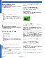
Louver SWING Button - Vertical
Air Flow Direction Adjustment
Press the SWING UP/DOWN button to choose the position of
the vertical airflow louvers.
Status display of air flow
COOL/DRY:
HEAT:
Caution:
•
It is advisable not to keep the vertical louver in the down-
ward position for an extended period of time in COOL or
DRY mode, otherwise condensate water may form on the
louver.
•
Note:
When turning the unit on, the remote control will automatically
return the louver to the previous set swing position. When turn-
ing the unit off, the louver will rotate to the full open position
prior to closing
.
10
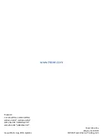
Louver SWING Button - Horizontal
Press the SWING UP/DOWN button to choose the position of
the horizontal airflow louvers.
Status display of air flow
COOL/DRY/HEAT:
'
Caution:
•
When humidity levels are high, condensate water may oc-
cur at the air outlet if all horizontal louvers are adjusted to
left or right.
Note:
When turning the unit on, the remote control will automatically
return the louver to the previous set swing position. When turn-
ing the unit off, the louver will rotate to the full open position
prior to closing
.
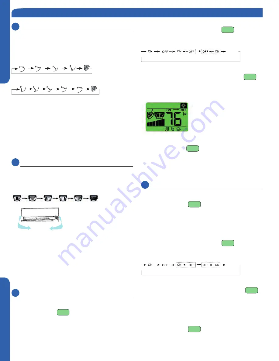
11
Timer ON Button
On-Off Operation
1. Start the unit and select the desired operating mode.
2. Press the TIMER ON
button to enter the TIMER ON
mode. The remote control will start flashing “ON”.
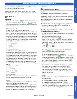
3. Every time the TIMER ON button is pressed the length of
time increases in 0.5 hour increments between hours 0 and
12, and 1 hour increments for times between hours 12 and
24.
4. Once the desired length of time is selected for the unit to
turn on, press the CONFIRM/CANCEL
to confirm
this setting.
The remote control display changes as follows:
BLANK
TIMER ON TIMER OFF
TIMER ON-OFF
TIMER OFF-ON
0.5h
0.5h
0.5h
0.5h
Cancel TIMER ON setting:
With a TIMER ON set, press the CONFIRM/CANCEL
button once to cancel the TIMER ON.
Turning the unit ON with the TIMER from it being OFF will look
like this on the remote control display:
Note:
Holding the TIMER ON
button down will rapidly cycle
the time. After replacing batteries or a power failure occurs,
the time setting will need to be reset.
According to the Time setting sequence of TIMER ON or
TIMER OFF, either Start-Stop or Stop-Start can be achieved.
12
Timer OFF Button
On-Off Operation
1. Start the unit and select the desired operating mode.
2. Press the TIMER OFF
button to enter the TIMER OFF
mode. The remote control will start flashing “OFF”.
3. Every time the TIMER OFF button is pressed the length of
time decreases in 0.5 hour increments between hours 0
and 12, and 1 hour increments for times between hours 12
and 24.
4. Once the desired length of time is selected for the unit to
turn off, press the CONFIRM/CANCEL
to confirm
this setting.
The remote control display changes as follows:
BLANK
TIMER ON TIMER OFF
TIMER ON-OFF
TIMER OFF-ON
0.5h
0.5h
0.5h
0.5h
Cancel TIMER OFF setting:
With a TIMER OFF set, press the CONFIRM/CANCEL
button once to cancel the TIMER OFF.
Turning the unit OFF with the TIMER from it being ON will look
like this on the remote control display:
Note:
Holding the TIMER OFF
button down will rapidly cycle
WIRELESS REMOTE CONTROLLER OPERATION


