•
Electrical Safety Requirements
Note:
1.
The surrounding conditions (ambient temperature, direct sunlight and rainwater) shall be noticed during
electrical wiring, with effective protective measures being taken.
2.
Copper wire cable in line with local standards shall be used as the power line and connector wire.
3.
Both the indoor unit and outdoor unit shall be reliably earthed.
4.
Wiring for the outdoor unit shall be made first and then the indoor unit. The air conditioner can only be
powered on after wiring and pipe connection.
5.
The dedicated branch circuit must be used, and leakage protector with sufficient capacity must be installed.
•
Qualification Requirements of Installer
Relevant qualification certificate must be obtained as per national laws and regulations.
•
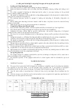
Indoor Unit Installation
1.
Fixation of wall panel and piping layout
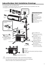
In case of left/right water pipe connection for the indoor unit, or in case the evaporator interface of the indoor
unit and the horn mouth of the connecting piping cannot be extended to the outdoor side for installation, the
connector pipes shall be connected to the evaporator piping interface of the indoor unit in the process of horn
mouth.
2.
Piping
layout
During layout of connecting pipes, drain hose and connector wires, the drain hose and connecting wire shall
be placed at the bottom and top respectively. The power line cannot be twined with the connector wire. The drain
pipes (especially inside the room and machine) must be winded with thermal insulation materials.
3.
Nitrogen charging for pressure maintaining and leak detection
After the evaporator of the indoor unit is connected to the connector pipe (after welding), nitrogen more than
4.0MPa shall be charged inside the evaporator and the piping connected to evaporator with a nitrogen cylinder
(adjusted by a reducing valve). Afterwards, the valve of the nitrogen cylinder shall be closed, for leak detection
with soapy water or leak detecting solution. The pressure shall be maintained for more than 5 minutes, and then
whether the system pressure is reduced or not shall be observed. In case the pressure is reduced, leakage can be
identified. After the leak point is handled, the steps above shall be repeated.
After the evaporator of the indoor unit is connected to connecting piping, nitrogen shall be charged for
pressure maintaining and leak detection. Afterwards, the evaporator shall be connected to the two-way stop valve
and three-way stop valve of the outdoor unit. After the copper cap of the connecting piping is fastened, nitrogen
more than 4.0MPa shall be charged at the access hole of the three-way stop valve with a charging hose. The valve
of the nitrogen cylinder shall be closed, for leak detection with soapy water or leak detecting solution. The
pressure shall be maintained for more than 5 minutes, and then whether the system pressure is reduced or not shall
be observed. In case the pressure is reduced, leakage can be identified. After the leak point is handled, the steps
above shall be repeated.
The operation above can also be completed after the indoor unit is connected to the connecting pipelines and
the two-way stop valve and three-way stop valve of the outdoor unit, after the access hole of the outdoor unit is
connected to the nitrogen cylinder and pressure gauge and after more than 4.0MPa nitrogen is charged. No leak
points are identified in the leak detection at the joint/welding junction of the indoor unit and at the joint of
connecting pipelines of the two-way stop valve and three-way stop valve of the outdoor unit. It must be
guaranteed that each joint is available for leak detection during installation.
The next step (vacuumizing with a vacuum pump) can only be continued after the installation steps (nitrogen
charging for pressure maintaining and leak detection normal) are completed.
•
Outdoor Unit Installation
1.
Fixation
and
connection
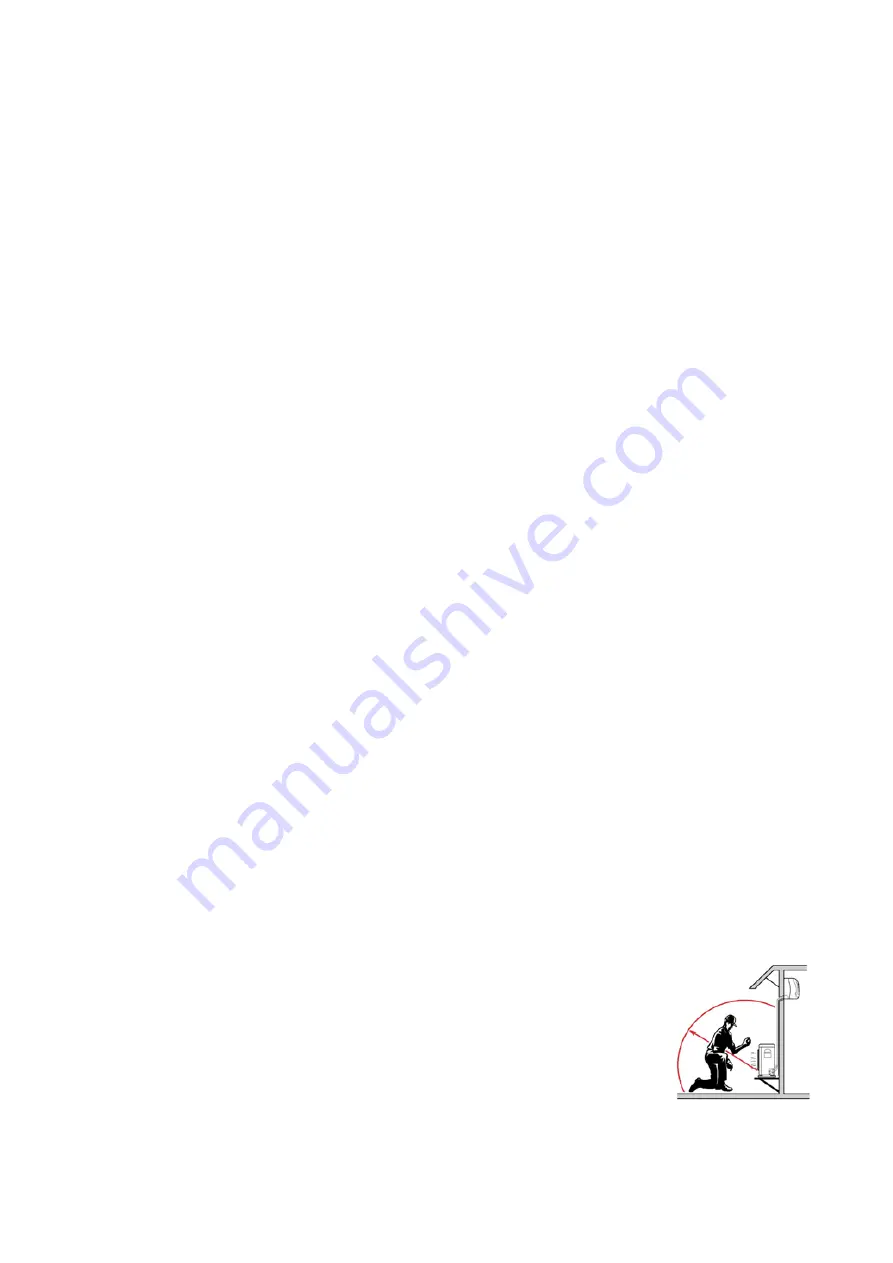
Note:
a)
Fire source shall be avoided within 3m around the place of installation.
b)
The leak detection equipment of refrigerant shall be placed at a low position in the
outdoor, and shall be opened.
5
Summary of Contents for 1U71S2SR2FA
Page 2: ......
Page 16: ...WARNING CAUTION N Open the window and well ventilated the room explosion proof fuse 13 ...
Page 18: ...R32 2 3 R 2 3 R R32 R32 R32 R32 R32 15 ...
Page 20: ...R32 R32 R32 R32 R32 R32 R32 R32 R32 17 ...
Page 21: ...3 R32 R32 R32 R32 R32 R32 R32 18 ...
Page 22: ...R32 R32 R32 R32 R32 R32 R32 R32 10A HFC 410A 19 ...
Page 25: ...22 ...
Page 26: ...23 R32 R32 ...


