2U14CS1ERA-SM
Service diagnosis
56
Domestic Air Conditioner
7.4.3 Indoor AC fan motor malfunction
Indoor Display E14
Method of
The rotation speed detected by the Hall IC during fan motor operation is used to
determine
Malfunction
abnormal fan motor operation
Detection
Malfunction when the detected rotation feedback singal don’t receiced in 2 minutes
Decision
Conditions
Supposed
Ƶ
Operation halt due to breaking of wire inside the fan motor .
Causes
Ƶ
Fan motor overheat protection
Ƶ
Operation halt due to breaking of the fan motor lead wires
Ƶ
Detection error due to faulty indoor unit PCB
Troubleshooting * Caution Be sure to turn off power switch before connect or disconnect connector,
or else parts damage may be occurred.
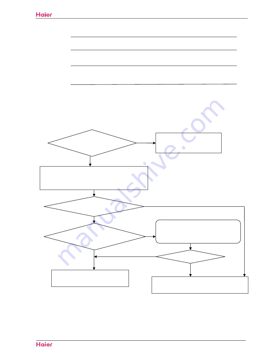
Check whether terminals
on indoor pcb is well ?
Electrify the machine again and turn it on in the cooling operation,
Measure voltage between the positions 1and 3 of Terminal CN2
on the indoor PCB
the voltage is about 90-220vac
check whether motor can run
when turn on the unit
the indoor motor is damaged and need replace
Yes
12
12
<HV
Measure whether there is voltage pulse(0-5VDC)
between the positions middle wire and black wire
of Terminal CN7 on the indoor PCB
12
the indoor pcb is damaged and need replace
Pull out the terminals on the indoor
mainboard and reinsert them.
1R
<HV
Is it ok?
<HV
Summary of Contents for 2U14CS1ERA
Page 44: ...41 2U14CS1ERA SM ...
Page 73: ...70 Domestic air conditioner WARNING CAUTION Installation 2U14CS1ERA SM ...
Page 74: ...71 Domestic air conditioner Installation 2U14CS1ERA SM ...
Page 77: ...Installation 2U14CS1ERA SM 74 Domestic air conditioner ...
Page 78: ...Installation 2U14CS1ERA SM 75 Domestic air conditioner ...
Page 79: ...Installation 2U14CS1ERA SM 76 Domestic air conditioner ...
Page 82: ...Installation 2U14CS1ERA SM 79 Domestic air conditioner ...
Page 86: ...83 Domestic air conditioner Removal of procedure 2U14CS1ERA SM ...
Page 89: ...86 Domestic air conditioner Removal of procedure 2U14CS1ERA SM three two HOOKS ...
Page 96: ... Domestic air conditioner Removal of procedure 2U14CS1ERA SM 8 ...
Page 98: ...Domestic air conditioner Removal of procedure 2U14CS1ERA SM 9 ...
Page 102: ...99 Domestic air conditioner Removal of procedure 2U14CS1ERA SM 10 ...
Page 103: ... Domestic air conditioner Removal of procedure 2U14CS1ERA SM 11 ...
Page 105: ...Domestic air conditioner Removal of procedure 2U14CS1ERA SM 102 12 ...
Page 110: ... SSHQGL 107 10 Appendix 10 1 Piping Diagrams 2U14CS1ERA SM ...
Page 111: ...Domestic air conditioner Wring Diagram 108 10 2 Wiring Diagrams Indoor 2U14CS1ERA SM ...


