2U14CS1ERA-SM
Service diagnosis
61
'RPHVWLF $LU &RQGLWLRQHU
7.4.8 Power Supply Over or under voltagve fault
outdoor display
:
LED1 flash 6 times The power supply is over voltage
Method of
An abnormal voltage rise or fall is detected by checking the specified voltage detection circuit.
Malfunction
Detection
Malfunction An voltage signal is fed from the voltage detection circuit to the microcomputer
Decision
Conditions
Supposed
Ŷ
Supply voltage not as specified
Causes
Ŷ
the IPM module is broken
Ƶ
the outdoor PCB is broken
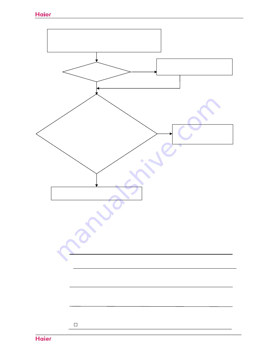
1) Check whether Terminal CN23 and CN24 on the outdoor mainboard
CN10 and CN11 on IPM module
2) Check whether the connected wire between IPM and outdoor
Are they good?
Electrify the machine again and turn it
on, Check whether the voltage between
1 and 2 of Terminal CN23 is about
DC5V,
Check
whether
the
voltage
between2 and 3 of Terminal CN23 is
about DC15V,
Replace the outdoor mainboard with a new one
Replace the outdoor IPM module
with a new one.
YES
NO
NO
YES
Malfunction unsolved
1) Pull out and reinsert the terminals.
2) Replace connected wire
Summary of Contents for 2U14CS1ERA
Page 44: ...41 2U14CS1ERA SM ...
Page 73: ...70 Domestic air conditioner WARNING CAUTION Installation 2U14CS1ERA SM ...
Page 74: ...71 Domestic air conditioner Installation 2U14CS1ERA SM ...
Page 77: ...Installation 2U14CS1ERA SM 74 Domestic air conditioner ...
Page 78: ...Installation 2U14CS1ERA SM 75 Domestic air conditioner ...
Page 79: ...Installation 2U14CS1ERA SM 76 Domestic air conditioner ...
Page 82: ...Installation 2U14CS1ERA SM 79 Domestic air conditioner ...
Page 86: ...83 Domestic air conditioner Removal of procedure 2U14CS1ERA SM ...
Page 89: ...86 Domestic air conditioner Removal of procedure 2U14CS1ERA SM three two HOOKS ...
Page 96: ... Domestic air conditioner Removal of procedure 2U14CS1ERA SM 8 ...
Page 98: ...Domestic air conditioner Removal of procedure 2U14CS1ERA SM 9 ...
Page 102: ...99 Domestic air conditioner Removal of procedure 2U14CS1ERA SM 10 ...
Page 103: ... Domestic air conditioner Removal of procedure 2U14CS1ERA SM 11 ...
Page 105: ...Domestic air conditioner Removal of procedure 2U14CS1ERA SM 102 12 ...
Page 110: ... SSHQGL 107 10 Appendix 10 1 Piping Diagrams 2U14CS1ERA SM ...
Page 111: ...Domestic air conditioner Wring Diagram 108 10 2 Wiring Diagrams Indoor 2U14CS1ERA SM ...


