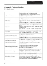
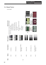


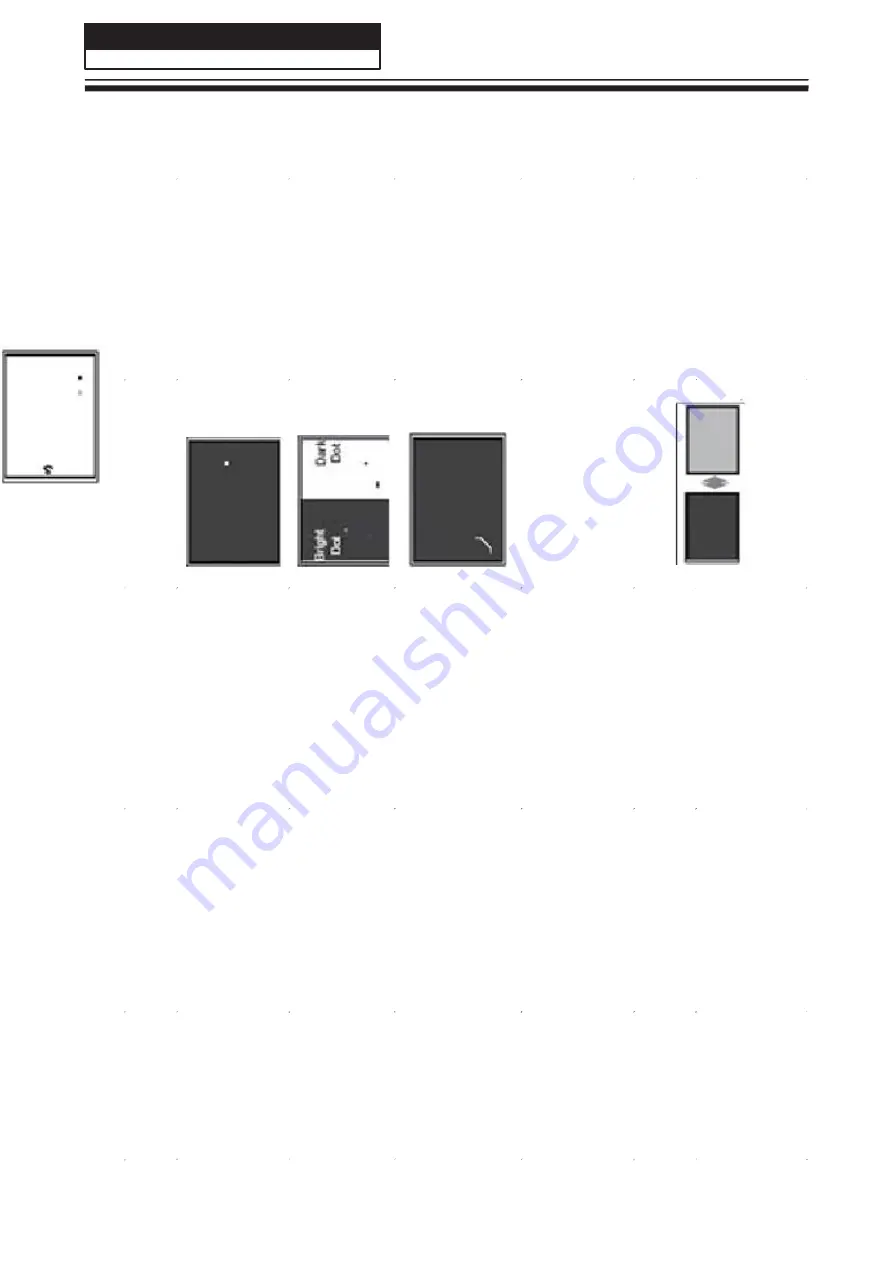
Des
c
ription
P
henome
na
Fai
lure
Ca
u
s
e
Bri
g
h
t
d
o
t
d
a
rk
d
o
t
in
p
a
n
n
e
l
In
c
o
m
in
g
I
n
s
p
e
c
ti
o
n
St
a
n
d
a
rd
Bl
a
d
d
e
r i
n
P
o
la
ri
z
e
r
Bl
a
d
d
e
r
b
e
twe
e
n
Po
la
ri
z
e
r
a
n
d
to
p
g
la
s
s
Po
la
ri
z
e
r S
c
ra
tc
h
Ti
n
e
o
r ri
g
id
it
y
a
ro
s
e
Ey
e
win
k
e
r
in
s
id
e
P
o
la
ri
z
e
r
Ey
e
win
k
e
r
in
s
id
e
P
o
la
ri
z
e
r
Ab
n
o
rm
a
l Di
s
p
la
y
Bri
g
h
t
a
n
d
d
a
rk
d
is
p
la
y
a
lte
rn
a
te
ly
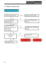
1
.Ch
ip
l
o
s
e
a
c
ti
o
n
2
.I
C a
h
o
rt
o
r
jo
in
ti
o
g
b
a
d
3
.Pa
n
n
e
l a
n
d
v
s
c
c
o
n
n
e
c
t
b
a
d
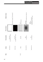
P
a
rt
Nam
e
Dot
De
fe
c
t
Po
la
ri
z
e
r Bu
b
b
le
Pa
n
e
l
o
r Po
la
rl
z
e
r
Po
la
ri
z
e
r S
c
ra
tc
h
F/
in
s
id
e
Po
la
ri
z
e
r
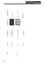
Ab
n
o
rm
a
l Di
s
p
la
y
Cir
c
u
it
Fl
a
s
h
in
g
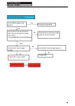
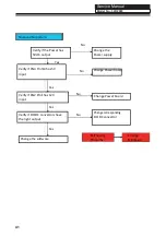
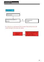
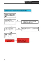
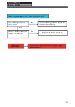
Service Manual
Model No.: 32D2000
46
Summary of Contents for 32D2000
Page 10: ...Service Manual Model No 32D2000 2 2 External pictures four faces Front Side Up Side 9 ...
Page 11: ...Service Manual Model No 32D2000 Right Side Back Side 10 ...
Page 17: ...Service Manual Model No 32D2000 TFT LCD Module 17 ...
Page 30: ...Service Manual 7 2 Wiring Connection Diagram 30 Service Manual Model No 32D2000 ...
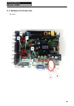
Page 36: ...Service Manual Model No 32D2000 9 2 Mainboard IC Introduction Top view 36 1 2 3 4 5 6 7 8 ...
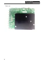
Page 37: ...Service Manual Model No 32D2000 Bottom view 37 ...


