background image


Service Manual 

Model No.: 


7-2 . Wiring Connection Diagram 


30

40D2000

Summary of Contents for 40D2000

Page 1: ...hnical individuals of potential dangers in attempting to service a product Products powered by electricity should be serviced or repaired only by experienced professional technicians Any attempt to service or repair the product or products dealt with in this service information by anyone else could result in serious injury or death 2014 Qingdao Haier Electronics Co Ltd All rights reserved Unauthor...

Page 2: ...ed in this manual 6 1 4 How to Read this Service Manual 6 Using icons 6 Chapter 2 Specification 2 1 Specification list 8 2 2 External pictures four faces 9 Chapter 3 Disassemble and Assemble 3 1 40D2000 11 3 1 1 Remove the Stand 11 3 1 2 Remove the Back Cabinet 11 3 1 3 Remove the Mainboard 11 3 1 4 Remove the Power Supply Module 11 3 1 5 Remove the Speaker 11 3 1 6 Remove the Remote Control Board 1...

Page 3: ...rical Parts 7 1 Block Diagram 23 7 2 Circuit Diagram 30 Chapter 8 Measurements and Adjustments 8 1 Service Mode 31 8 1 1 How to enter into Service Mode 31 8 1 2 How to exit 31 8 2 Measurements and Adjustments 31 8 2 1 The Main Menu 31 8 2 2 General Setting 32 8 2 3 Picture 32 8 2 4 Sound 33 8 2 5 Debug 33 8 3 Software Update 34 8 3 1 T VST59 software update 34 Chapter 9 Trouble shooting 9 1 Simple...

Page 4: ...ist up the potential hazard or risk for the service personnel to open the units and disassemble the units For example we need to describe properly how to avoid the possibility to get electrical shock from the live power supply or charged electrical parts even the power is off This symbol indicates that high voltage is present inside It is dangerous to make any king of contact with any inside part ...

Page 5: ... removing an electrical assembly equipped with ES devices place the assembly on a conductive surface such as aluminum foil to prevent electrostatic charge buildup or exposure of the assembly 1 3 4 About lead free solder PbF This product is manufactured using lead free solder as a part of a movement within the consumer products industry at large to be environmentally responsible Lead free solder mu...

Page 6: ...rength CAUTION This is a flammable mixture Unless specified otherwise in this service manual lubrication of contacts is not required Capacitors may result in an explosion hazard 5 Do not defeat any plug socket B voltage interlocks with which receivers covered by this service manual might be equipped 6 Do not apply AC power to this instrument and or any of its electrical assemblies unless all solid s...

Page 7: ...ize bodily motions when handling unpackaged replacement ES devices Otherwise harmless motion such as the brushing together of your clothes fabric or the lifting of your foot from a carpeted floor can generate static electricity sufficient to damage an ES device 1 3 7 Ordering Spare Parts Please include the following informations when you order parts Particularly the Version letter 1 Model number ser...

Page 8: ...y damage equipment loose data get an unexpected result or has to restart part of a procedure Warning A warning is used when there is danger of personal injury Reference A reference guides the reader to other places in this binder or in this manual where he she will find additional information on a specific topic 7 40D2000 ...

Page 9: ... Audio System MN Audio Output Power Built in W 8W 2 Audio Output Power outer W No Total Power Input W 60W Voltage Range V AC100V 240V Power Frequency Hz 50 60Hz Time of Sleep Timer MINS 240Min Net Weight KG 17 8lbs Gross Weight KG 20 9lbs Dimensions with Stand 29 25 x 19 44 x 6 69 Dimensions without Stand 29 25 x 17 48 x 3 19 Service Manual Model No Chapter 2 Specification 2 1 Specification list 8 4...

Page 10: ...Service Manual Model No 2 2 External pictures four faces Front Side Up Side 9 40D2000 ...

Page 11: ...Service Manual Model No Right Side Back Side 10 40D2000 ...

Page 12: ...he stand which in the picture above 3 Remove the stand 3 1 4 Remove the Power Supply Module 3 1 2 Remove the Back Cabinet 1 Remove the five screws indicated with red circles in below picture 2 Remove the Power Supply Module 3 1 5 Remove the Speaker Remove the Speaker indicated by red circle in below picture 1 Remove the sixteen screws indicated with red circles 2 Flip machine panel side up 3 Caref...

Page 13: ...Service Manual Model No 3 1 6 Remove the Remote Control Board And the Key Board Remove the Remote Control Board and the Key Board indicated by red circle in below picture 12 40D2000 ...

Page 14: ...Service Manual Model No Chapter 4 Location of Controls and Components 4 1 Board Location 13 B Panel A Board B No Model Description A Board Mainboard B Panel LCD Panel 40D2000 DH1UF0D0700M 6047300025 ...

Page 15: ...or equipment then translate into signal that panel can Display 4 2 2 Connector definition CN18 CN6 14 IR Key Interface CN6 Pin number Signal name 1 5V 2 RED 3 GRE 4 IR 5 GND 6 K0 7 K1 8 K2 9 K3 10 K4 11 K5 12 K6 13 K7 14 GND Speaker connector CN18 Pin number Signal name 1 ROUT 2 ROUT 3 LOUT 4 LOUT 40D2000 ...

Page 16: ...Service Manual Model No 4 3 LCD Panel Backlight Unit LVDS CONNECTOR CN1 Connector Definition 16 40D2000 ...

Page 17: ...Service Manual Model No TFT LCD Module 17 40D2000 ...

Page 18: ...Service Manual Model No Chapter 5 Installation Instructions 5 1 Accessories Remote Control 18 Batteries 40D2000 ...

Page 19: ...ct HDMI mode Refer to the HDMI device user guide for how to operate C Connect a D type 15 pin VGA interface cable to the VGA video interface connector on the PC Connect the other end of the cable to the PC interface connector on the TV Tighten the screws on the D E VGA connectors and connect the audio cable not supplied to the audio input socket on the back of the TV Turn on the TV firstly and then...

Page 20: ...l the vailable input sources 3 MENU Press to select the main menu 4 CH TV channel down 5 CH TV channel up 6 VOL Press to decrease the volume 7 VOL Press to increase the volume Service Manual Model No Chapter 6 Operation Instructions 6 1 Front Panel Controls 20 40D2000 ...

Page 21: ...ervice Manual Model No 6 2 Back Panel Controls 21 1 Earphone output 2 Line output 3 Coax output 4 AV output 5 YPbPr input 6 HDMI1 input 7 HDMI2 MHL input 8 HDMI3 input 9 VGA input 10 PC Audio input 11 RF input 12 USB input 40D2000 ...

Page 22: ...Service Manual Model No 6 3 Setting Up Your Remote Control When using the remote control aim it towards the remote sensor on the TV 22 40D2000 ...

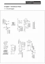
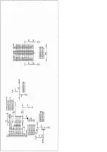
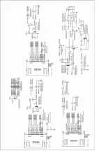
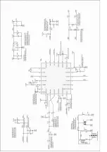
Page 23: ...Service Manual Model No Chapter 7 Electrical Parts 7 1 Circuit Diagram 40D2000 ...

Page 24: ......

Page 25: ......

Page 26: ......

Page 27: ......

Page 28: ......

Page 29: ......

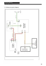
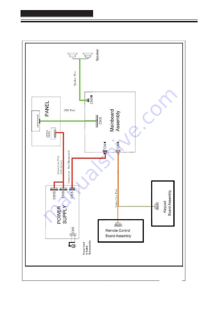
Page 30: ...Service Manual Model No 7 2 Wiring Connection Diagram 30 40D2000 ...

Page 31: ...end of the main factory menu you can see the edition of the software like this BUILD TIME 2013 02 28 16 35 37 VERSION v1 0 8 1 2 How to exit If you want to exit this factory menu please press the button Exit on the remote system will be out the factory mode menu 8 2 Measurements and Adjustments 8 2 1 The Main Menu In factory mode menu press up down button to choose the up down item press right or ...

Page 32: ...oose on or off in Dynamic Contrast 6 Power On Mode Choose on or off in Power On Mode 7 Mirror Control Choose on or off in Mirror Control 8 Front End Status 9 Timer Test 10 SSC 11 Erase Flash 12 PQ Advance Debug Choose on or off in PQ Advance Debug 13 Factory remote Open or close the Factory remote 14 Factory CH Export 8 2 3 PICTURE Adjust the Picture Mode Picture Curve White Balance and OverScan i...

Page 33: ...nd Mode Volume Curve Audio Output and True Volume in different source 8 2 5 Panel Setting 1 LVDS Bit Mode choose the Bit 2 LVDS MAP choose the MAP 3 LVDS ODD Even choose ODD or Even 4 Bcaklight Adiust the value of backlight 5 Reset Panel Setting Date 33 40D2000 ...

Page 34: ...s to a USB disk on the root directory 2 Insert the USB disk when the AC power is off 3 Turn on the AC power in turn to begin 4 Turn off the AC power until the indicator light fast twinkling 5 Pull out the USB disk and power on the television Note Do not turn off the TV while it is updating 34 40D2000 ...

Page 35: ... by Fine Tune and MANUAL Scan No color for some channel program black and white Verify that the same problem exists on other channels Check the picture and sound systems Refer to the relevant instructions in the manual to adjust the colour Spots with some or all pictures Verify if the antennal is correctly connected Verify if the antennal is in good condition Make fine adjustment of channel Televis...

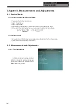
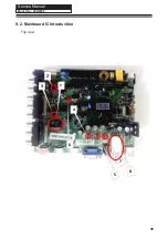
Page 36: ...Service Manual Model No 9 2 Mainboard IC Introduction Top view 36 1 2 3 4 5 6 7 8 40D2000 ...

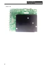
Page 37: ...Service Manual Model No Bottom view 37 40D2000 ...

Page 38: ... DC DC convertor 5V 1 8V for MSD3393LU U1 LC1117CLTRAD UL2 5 voltage convertor 5V to 3 3V_STB LC1117CLTR33 UL1 6 voltage convertor 5V to 1 15V_STB LC3406CB5TR UD1 7 voltage convertor 5V to 3V for tuner LC1117CLTR33 UT1 8 Tuner SDCL1005CR33JTDF RFT1 Please check the Schematic Diagram for the particular support 38 40D2000 ...

Page 39: ... the Power Board Yes Check the CN2 BLO Backlight on off Yes No There s something wrong with FRC Verify if the DC DC convertor can output the right Voltage No Change the corresponding DC DC QB3 output 5V Yes No Verify if QM1 output Change the QM1 Yes Still having problems Change Panel Change LVDS wire 39 40D2000 ...

Page 40: ...rify if the main board has the right input according to the source TV COMPONENT AV VGA HDMI etc Yes Verify if UA1 has the right output Yes Check CN17 input is right No No Check the corresponding audio input circuit you connect Verify if UA1 has the right power in No Change UA1 Still having problems Change Mainboard 40 40D2000 ...

Page 41: ...he Power supply Verify if CN4 Pin3 4 has 5V input Yes Verify if CN2 Pin1 has 12V input Yes Verify if DC DC convertors have the right output Yes No No No Change Power board Change Power board Change corresponding DC DC convertor Still having Change Change the software 41 Problems Mainboard 40D2000 ...

Page 42: ...ify if sound system is correct No Change sound system For ease of use recommend that customer format the picture and sound settings in the automatic option Still having problems Updata the software and make the reboot or change the maiboard 42 40D2000 ...

Page 43: ...me problem exists in other channels Yes check out of picture and sound system No No Check out of picture and sound system of this channel Change the channel to the right sound system Yes Refer to relative instructions in the Manual for color adjust Updata the software and Still having problems 43 make the reboot or change the maiboard 40D2000 ...

Page 44: ...en Check if the power cord co nnect well Yes Check if the Power board output 5V and 12V No No Reconnect the power cord with the outlet or Power board Replace the Power board pls Still having problems Check if Main board LVDS wire Panel are in good condition 44 40D2000 ...

Page 45: ...LCD Mis align between TCP and Panel Panel failure TCP failure Name Description Phenomena Failure cause V B D Vertical bar V Dim Vertal gray line V L D Vertical color line light or dark forever TCP H B D Horizontal bar H Dim Horizontal gary line H L D Horizontal line light or dark forever Service Manual Model No 9 4 Pannel Failure Failure Mode 45 40D2000 ...

Page 46: ...tch Tine or rigidity arose Eyewinker inside Polarizer Eyewinker inside Polarizer Abnormal Display Bright and dark display alternately 1 Chip lose action 2 IC ahort or jointiog bad 3 Pannel and vsc connect bad Part Name Dot Defect Polarizer Bubble Panel or Polarlzer Polarizer Scratch F inside Polarizer Abnormal Display Circuit Flashing Service Manual Model No 46 40D2000 ...

Page 47: ...EDS Black Screen B L normal only Black screen display Circuit Crosstalk FIIcker LCD Vcom imbalance Abnormal Color Only color abormal Capacitance improper bring crosstalk inside LCD pannel Abnormal Color Only color abnormal 1 Chip lose action 2 IC short or jointion bad 3 Pannel and vsc connect bad Service Manual Model No 47 40D2000 ...

Page 48: ...wire and electrode B L dark B L brightness darker than normal Connect badnessShort between wire and electrode B L wire damaged Without backlight B L wire damaged B L wire open Operation abnormal or systemic noise Operation abnormal or systemic noise Short bitween lamp housing and wire Because consume power too much B L shut down B L shutdown in sometime F M F M inB L white balck Rotundity or wirel...

Page 49: ...leakage B L unit badness Brightness at bottom of LCM brighter than normal Mechanlcal or B L B L brightness asymmetric Uniformity Sheet in B L unit is uneven Mount hole Lack screw or screw damage Lack screw Screw damage Service Manual Model No 49 40D2000 ...

Page 50: ...Sincere Forever Haier Group Haier Industrial Park No 1 Haier Road 266101 Qingdao China http www haier com Printed in China ...

Reviews: