Service Manual
Model No.:
components commonly are called Electrostatically Sensitive (ES) Devices. The following
techniques should be used to help reduce the incidence of component damage caused by
electros static discharge (ESD).
Electrostatically Sensitive (ES) Devices
Some semiconductor (solid-state) devices can be damaged easily by static electricity. Such
components commonly are called Electrostatically Sensitive (ES) Devices. Examples of typical
ES devices are integrated circuits and some field-effect transistors and semiconductor "chip"
components. The following techniques should be used to help reduce the ncidence of component
damage caused by static by static electricity.
1. Immediately before handling any semiconductor component or semiconductor-equipped
assembly, drain off any electrostatic charge on your body by touching a known earth ground.
Alternatively, obtain and wear a commercially available discharging wrist strap device, which
should be removed to prevent potential shock reasons prior to applying power to the unit under
test.
2. After removing an electrical assembly equipped with ES devices, place the assembly on a
conductive surface such as aluminum foil, to prevent electrostatic charge buildup or exposure of
the assembly.
1-3-4. About lead free solder (PbF)
This product is manufactured using lead-free solder as a part of a movement within the
consumer products industry at large to be environmentally responsible. Lead-free solder must be
used in the servicing and repairing of this product.
1-3-
5. Use the genewing parts (specified parts)
Special parts which have purposes of fire retardant (resistors), high-quality sound (capacitors),
low noise (resistors), etc. are used.
When replacing any of components, be sure to use only manufacture's specified parts shown in
the parts list.
Safety Component
● Components identified by mark have special characteristics important for safety.
1-3-6 Safety check after repairment
Confirm that the screws, parts and wiring which were removed in order to service are put in the
original positions, or whether there are the positions which are deteriorated around the serviced
places serviced or not. Check the insulation between the antenna terminal or external metal and
the AC cord plug blades. And be sure the safety of that.
General Servicing Precautions
4
40D2000
Summary of Contents for 40D2000
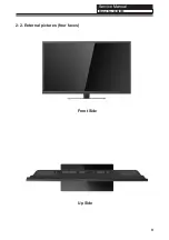
Page 10: ...Service Manual Model No 2 2 External pictures four faces Front Side Up Side 9 40D2000 ...
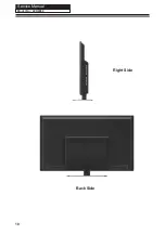
Page 11: ...Service Manual Model No Right Side Back Side 10 40D2000 ...
Page 17: ...Service Manual Model No TFT LCD Module 17 40D2000 ...
Page 23: ...Service Manual Model No Chapter 7 Electrical Parts 7 1 Circuit Diagram 40D2000 ...
Page 24: ......
Page 25: ......
Page 26: ......
Page 27: ......
Page 28: ......
Page 29: ......
Page 30: ...Service Manual Model No 7 2 Wiring Connection Diagram 30 40D2000 ...
Page 36: ...Service Manual Model No 9 2 Mainboard IC Introduction Top view 36 1 2 3 4 5 6 7 8 40D2000 ...
Page 37: ...Service Manual Model No Bottom view 37 40D2000 ...


