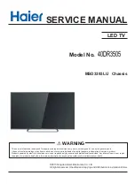


Service Manual
Model No.: 39D3005
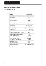
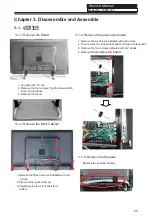
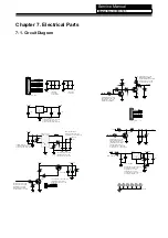
Chapter 3. Disassemble and Assemble
3-1.
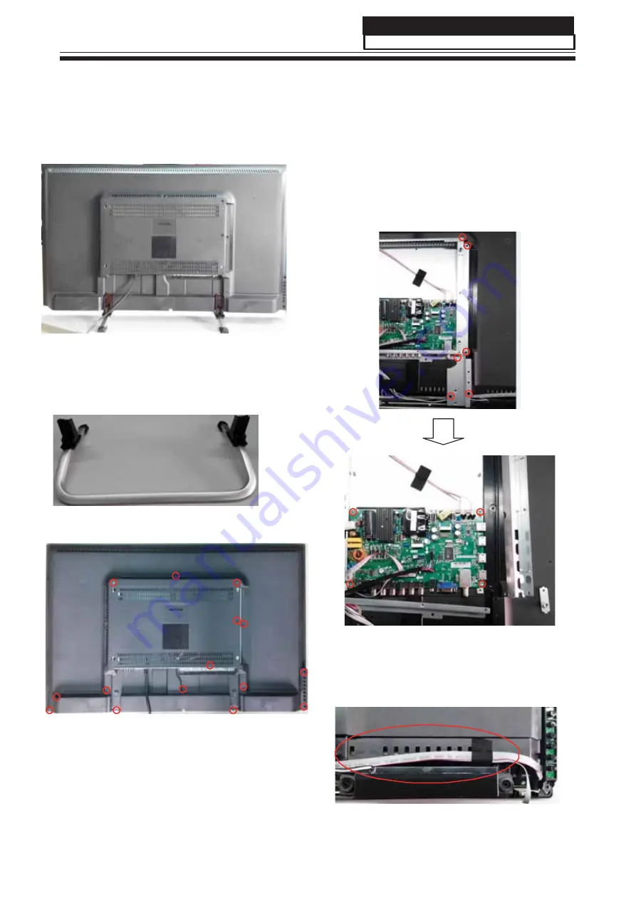
3-1-1. Remove the Stand
3-1-3. Remove the power-main board.
1. Remove the six screws indicated with red circles.
2. Then remove the side metal board and down metal board.
3. Remove the four screws indicated with red circles.
4. Remove
the power-main board.
1. Lay down the TV set .
2. Remove the four screws from the stand which
in the picture above.
3. Remove the stand.
3-1-2. Remove the Back Cabinet
3-1-4. Remove the Speaker
Remove the speaker directly
1.Remove the fifteen screws indicated with red
circles.
2.
Flip machine, panel side up.
3.Carefully raise the Front shell from
bottom.
11
40DR3505
Model No.:
40DR3505
Summary of Contents for 40DR3505
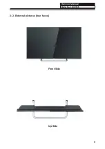
Page 10: ...Service Manual Model No 2 2 External pictures four faces Front Side Up Side 9 40DR3505 ...
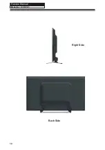
Page 11: ...Service Manual Model No Right Side Back Side 10 40DR3505 ...
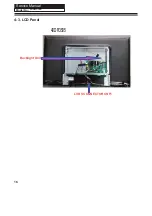
Page 16: ...Service Manual Model No 15 40DR3505 ...
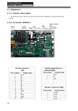
Page 17: ...Service Manual Model No 4 3 LCD Panel Backlight Unit LVDS CONNECTOR CNF1 16 40DR3505 40DR3505 ...
Page 18: ...Service Manual Model No 17 40DR3505 ...
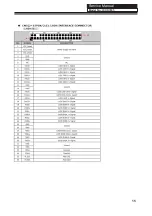
Page 31: ...Service Manual Model No 7 2 Wiring Connection Diagram 30 40DR3505 ...
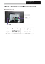
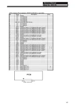
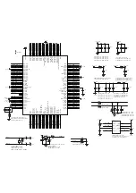
Page 37: ...Service Manual Model No 9 2 Mainboard IC Introduction Top view 36 1 2 3 4 5 6 7 8 40DR3505 ...
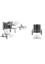
Page 38: ...Service Manual Model No Bottom view 37 40DR3505 ...


