background image


SERVICE MANUAL

Model: 

9

Issue 

Rev. 

Hinged (r =right l =left) / 
reversible 


R/R 

R/R 

R/R 

R/R 

R/R 

R/R 

Lock 

yes/no 

Freezing compartment 
integrated with door   


N N  N 

Y N 

Shelves: 


Number Fridge / 
Freezer  


3/ - 

3/ - 

3 / - 

3 / - 

3 / - 

3 / - 

Type (gr=grill / g=glass 
/ p=plastic) 


 g 

 g 

 g 

 g 

 g 

 g 

Colourw-white / b=blue 
/ g=green / t=transpar. 


t t t  t 

t t 

Adjustable (Y=yes / 
N=not) 

yes/no 

Foldable Shelf 

yes/no 

Bottle Rack 

yes/no 

Drawers: 


Plastic drawers (fully 
freezing comp.) 

n°. 

half freezing comp   

n°. 


Colour of drawer   
(w=white/t=transp./g=gr
een) 


w w w  w 

w w 

Crisper: 


Chiller / Meat (salad 
crisper)   transparent 
/ white 


 t 

t t 

Vegetable crisper(s)    
transparent / white 


Equipment & 
accessories 


Control panel: 


Power on/off 


Y Y Y  Y 

Y Y 

Interior / exterior 


Exterior 

Exterior 

Exterior 

Exterior 

Exterior 

Exterior 

Display type 


Display on door 

Display on door 

Display on door 

Display on door 

Display on door 

Display on door 

Control Type 


LED 

LED 

LED 

LED 

L

ED


L

ED


Control lamps                 
green& yellow / white 


white 

white 

white 

white 

white


white


Over temperature 
alarm freezer LED / 
Acoustic 


 - 

 - 

 - 

 - 

 - 

 - 

Door open alarm fridge   
LED / Acoustic 


Fast freeze switch 
/-function 


Fast cooling 


Holiday function 


Deodorizing 


N N N  N 

N N 

UV-light 


N N N  N 

N N 

Icon-sliver 


N N N  N 

 N 

 N 

Summary of Contents for A2FE635CFJRU

Page 1: ...experienced repair technicians only and is not designed for use by the general public It does not contain warnings and cautions to advice non technical individuals of potential dangers in attempting to service a product Product powered by electricity should by serviced or repaired only by experienced professional technicians Any attempt to service or repair the product or products dealt with in th...

Page 2: ...r door Freezer door 15 3 2 Adjustable foot 18 3 3 Maintenance 18 4 Disassembly 20 4 1 A2FE635CFJRUFreezer door assembly 20 4 2 Display screen assembly 21 4 3 Air passage assembly 21 4 4 Compressor assembly 23 4 5 Disassembly method of heating wire for defrosting 24 5 Control and display system 25 5 1 Control and display panel 25 5 2 Function adjustment 25 5 3 Error code display and sensor position...

Page 3: ... flow chart 34 7 2 Refrigeration flow scenograph 35 7 3 Air flow scenograph 36 7 4 Water supply flow scenograph 36 8 Circuit diagram 37 8 1 Brief principle diagram 37 8 2 Main control PCB diagram 38 9 Quick check 39 9 1 Self test model 39 9 2 PCB checkout 40 10 Trouble shooting 43 10 1 Abnormal phenomena 43 ...

Page 4: ... off This symbol indicates that high voltage is present inside It is dangerous to make any king of contact with any inside part of this product This symbol indicates that there are important operating and maintenance instructions in the literature accompanying the appliance 1 2 2 Be careful to the electrical shock To prevent damage which might result in electric shock or fire do not expose this co...

Page 5: ... you check something at a lower position 6 Take out every part in the cabinet before moving the machine especially things like panels e g glass shelf 7 Please wear intact cotton gloves when repair any parts of the evaporator so that scratches by the sharp fins can be avoided 8 If there is a breakdown with the refrigeration system please surrender the machine to the service center else the leaked r...

Page 6: ...s are used to attract the attention of the reader to specific information The meaning of each icon is described in the table below Note A note provides information that is not indispensable but may nevertheless be valuable to the reader such as tips and tricks Caution A caution is used when there is danger that the reader through incorrect manipulation may damageequipment loosedata get an unexpect...

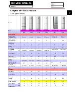
Page 7: ... 595 670 1905 595 670 1905 595 670 1905 595 670 1998 595 672 1998 595 672 Total net capacity L 347 352 352 352 369 374 Climate class SN T SN T SN T SN T SN T SN T Freezer compartment Star rating 4 4 4 4 4 4 Approvals VDE TÜV IMQ NF ÖVE DEMKO etc TÜV GS Rhl TÜV GS Rhl TÜV GS Rhl TÜV GS Rhl PCT PCT PCT PCT PCT PCT Certifications CE ISO 9001 2 CE ISO 9001 CE ISO 9001 CE ISO 9001 CE ISO 9001 CE ISO 90...

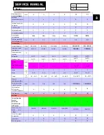
Page 8: ...ange from to C Refrigerator 2 8 C 2 8 C 2 8 C 2 8 C 2 8 C 2 8 C Vegetable Crisper 2 8 C 2 8 C 2 8 C 2 8 C 2 8 C 2 8 C My zone 3 mode Thaw Q cool Ch iller yes no Y Y Y Y Y Y Tem 2 3 2 3 2 3 2 3 2 3 2 3 Chiller yes no Y Y Y Y Y Y Chiller C 2 3 2 3 2 3 2 3 2 3 2 3 Freezer 16 24 C 16 24 C 16 24 C 16 24 C 16 24 C 16 24 C 16 24 C Features DIN 8950 resp 8953 Energy consumption EN 153 per 24h kWh 0 95 0 9...

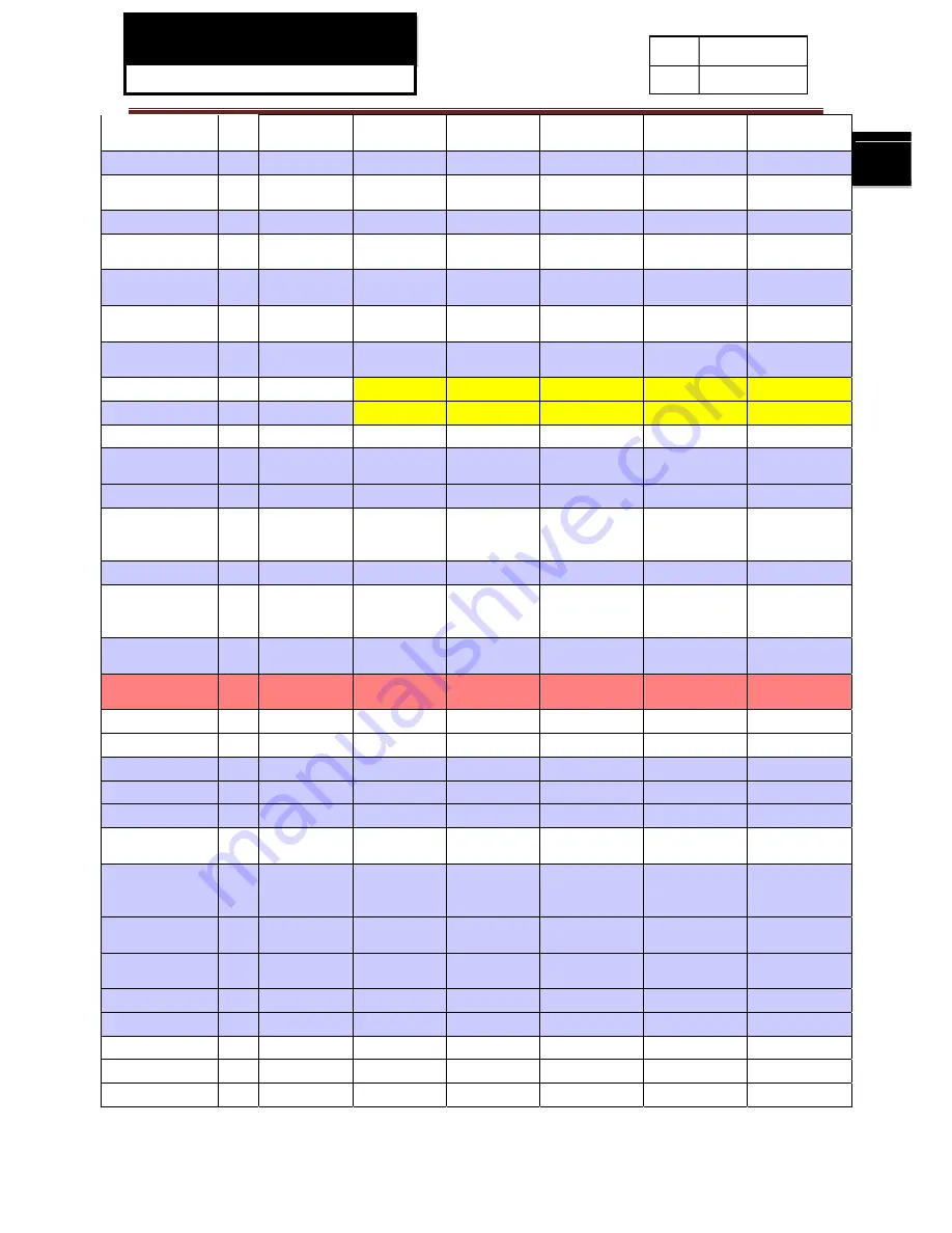
Page 9: ...een w w w w w w Crisper Chiller Meat salad crisper transparent white t t t t t t Vegetable crisper s transparent white t t t t t t Equipment accessories Control panel Power on off Y Y Y Y Y Y Interior exterior Exterior Exterior Exterior Exterior Exterior Exterior Display type Display on door Display on door Display on door Display on door Display on door Display on door Control Type LED LED LED LE...

Page 10: ...pth with open door mm 1204 1204 1204 1204 1204 0 1204 0 Door open angle n 125 125 125 125 125 125 Crisper fully extension with door open angle n 125 125 125 125 125 125 Net weight kg 84 80 80 80 86 83 Packing dimensions loadability Packing dimensions H W D cm 200 66 3 74 1 200 66 3 74 1 200 66 3 74 1 200 66 3 74 1 210 66 3 74 1 210 66 3 74 1 Gross weight kg 92 88 88 88 96 0 93 0 40 Container load ...

Page 11: ...SERVICE MANUAL Model 11 Issue Rev ...

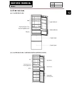
Page 12: ...SERVICE MANUAL Model 12 Issue Rev 2 2 External views 2 2 1 A2FE635CFJRU 2 2 2 C2FE636CFJRU C2FE636CSJRU C2FE636CWJRU ...

Page 13: ...SERVICE MANUAL Model 13 Issue Rev 2 2 3 A2FE637CXJRU 2 2 4 C2FE637CXJRU ...

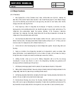
Page 14: ...dopting fully air cooled refrigeration system deep cooling and quick freezing 5 Quick cool function the refrigerating chamber can be adjusted to quick cool status after being at this status it will automatically turn on the function of quick cool and make the food go through the max ice crystal zone and thus effectively reserve the nutrition 6 Holiday function when you are out for holiday refriger...

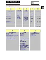
Page 15: ...lt C2 2D Gen 2 6 A 31 305 314 lt D1 Double doors Gen 1 32 315 324 lt 33 325 334 lt 35 345 354 lt 36 355 364 lt C X J SPECIAL FEATURES COLOUR HANDLES A Without chiller W White J Recessed integrated C Chiller T Titanium T External I Automatic Ice Device ice maker with water tank in the fridge S Silver E Easy handles T ATD Adj T Drawer X Inox Stainless steel W Water through the door G Glass Transpare...

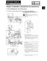
Page 16: ...gerator compartment 3 2 Water pipe 3 3 Water supplied time A Unscrew the four screws which secure the front panel located at the top B Push the front panel upward to withdraw the front panel C Pull the hinge cover upward D Disconnect the two connected terminals of electric cable E Push the small cover on the right side of the front panel by one hand to withdraw the small cover ...

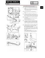
Page 17: ...it to the electric cable which is extending from the cabinet above the cabinet A Click fit the hinge cover firstly to clip the electric cable into the hinge cover then clip it to the hinge B install the small cover to the right side of the front panel from bottom to top direction C Click fit the front panel from top to bottom direction applying pressure on several points to secure the bottom clips...

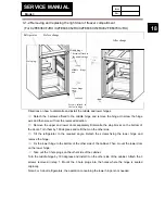
Page 18: ... Tilt the refrigerator to the required angle Detach the screws fixing the lower hinge and remove the hinge Fix the lower hinge to the bottom of the other side of the cabinet Then mount the lower door on the lower hinge Take out the 3 hole plugs on the other side of the cabinet Turn the middle hinge by 180 degrees and install it on the other side of the cabinet Attach the 3 screws removed in step 1...

Page 19: ...hor spon rator surface ean heavy When herefrigerato the floor htherefrigera h wirebrus acidor a or warm wa etalparts w anthecoldgl raturechang terruption stored inther e placed on d fire resis e refrigerato r by turning t ual operatio egularlytopre erefrigerator ngewithwarm eswith adry s nyouaremov or uprightdu atorwithwate h detergen alkalinesolu ater and a m withwethand ass shelve geandcause ref...

Page 20: ...rwill uality offood dfor anexten emethoddes en topreven therefrigerat ssary oliday or va tion pleased erwards clea artment from ertylossmay nthefridgesto th adhesivet tormorethan itshandletoa ghorizontally owercompan duringapo andtheinte efridgestora riseduringa dwillbereduc ded period scribed abov ntanyfoodre tor itis rec acation disconnectth ananddrythe mproducing qualifiedse ybecausedd oragecom...

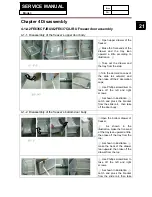
Page 21: ...caps Use Phillips screwdriver to take off the left and right screws As shown in illustration catch and pluck the bracket from the slide rail then take off the door body 4 1 2 Disassembly of the freezer s bottom door body Open the bottom drawer of freezer As shown in the illustration make the front end of the tray lean upward a little then take off the tray from the top As shown in illustration mak...

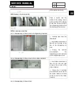
Page 22: ...r Carefully take down the lampshade Use Phillips screwdriver to take off the 2 screws on the top of the refrigerating air duct Unplug the terminal connectedwith the refrigerating air duct and take off the refrigerating air duct 4 3 2 Disassembly of the air duct of the chiller chamber Use Phillips screwdriver to take off the left and right screws of the air duct of the chiller chamber Unplug the 2 ...

Page 23: ... Pull out 4 slide rails and uplift the bottom of the air duct slightly make the right side onward a little and take off the air duct of the freezer a little Unplug the 2 terminals connected with the air duct of the freezer Make the air duct of the freezer slide from the bottom 4 3 5 Disassembly of the freezer fan Prize up the upper and down cover boards of the air duct of the freezer gently from t...

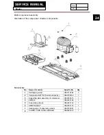
Page 24: ...terial Specific No Qty 1 Self tapping screw 0060112284 3 2 Compressor NX1116Y Include Capacity 0060702332 1 3 Supporting plate assembly of compressor 0060830615 1 4 SCREW 0060600186 1 5 Evaporating utensil 0060222122 1 6 DAMPING MAT 0060220107 1 7 Heating pipe of evaporating utensil 0060703847 1 8 POWER CORD FIXING RUBBER 0060405012 1 ...

Page 25: ... connected with the defrosting cable in the red circles As the red circle shown in illustration gently break apart the 2 chips which are used to fix the defrosting and heating wire and then get the defrosting and heating wire to go through the right chip Make the defrosting and heating wire go through the left chip ...

Page 26: ...nces through 2 3 4 5 6 7 8 2 The refrigerator temperature range is from a minimum value of 2 to a maximum value of 8 Stop to press A2 to confirm the set temperature Freezerstoragetemperaturesetup Press key A1 repeatedly until indicators C inlluminates press A2 to set the freezer temperature corresponding indicators C and D begin to flash simultaneously The temperature reduces by 1 by each single p...

Page 27: ... of the Holiday Function This function can be disabled by repeating the activation procedure manually In Holiday mode the refrigerator compartment operates at a temperature of 17 automatically In this mode the Holiday Function will be disabled by the operation of setting the refrigerator temperature My Zone Q cool Function Press key A3 repeatedly until indicators F begin to flash press A4 to confi...

Page 28: ... left open for over 7 minutes the internal light automatically switches off Turningoff on theRefrigerator When the refrigerator is working if you press key A4 for 5 seconds the whole refrigerator will be switched off The buzzer will begin to beep after pressing key A3 for 5 seconds The whole refrigerator will stop to work after the beep When the refrigerator is switched off if you press key A4 for...

Page 29: ...ey of Temp Set to display next code After the malfunction code is displayed every time you press the key of Temp Set it will display AT SNR R SNR S SNR F SNR D SNR practical temperatures one by one Notes if no malfunction then it will display the practical temperatures of each sensor directly after entering The following table shows the display methods of each sensor Sensor Display method Displaye...

Page 30: ... displayed through 4 functional icons as shown in the following table Represent ative No Displayed icon Lighted icon Represent ative No Displayed icon Lighted icon 0 0 None 0 5 S Cool D Frost 0 1 S Cool 0 6 Q Cool D Frost 0 2 Q Cool 0 7 S Frz D Frost 0 3 S Frz 0 8 S Cool S Frz D Frost 0 4 D Frost 0 9 Q Cool S Frz D Frost Log out method after entering into this mode press the key of Temp Zone again...

Page 31: ...t of refrigerating chamber 3 F SNR error F4 F SNR short circuit or open circuit Air duct of freezerchamb er 4 S SNR error F5 S SNR short circuit or open circuit Air duct of chiller chamber 5 D SNR error F6 D SNR short circuit or open circuit Evaporator 6 Communication error E0 No signal More than 2 minutes 7 F FAN error E1 No signal More than 10 seconds 8 C FAN error E2 No signal More than 10 seco...

Page 32: ...istance to the left side mm Environment temperature sensor 13 286 309 Refrigerating sensor 390 194 401 Freezing sensor 1270 112 483 Chiller sensor 912 5 203 392 Defrosting sensor 1275 461 134 Fridge storage temperature sensor Ambient temperature sensor Freezer storage temperature sensor Defrosting temperature sensor Chiller temperature sensor ...

Page 33: ...erating chamber continuously opens for 60minutes or the temperature of the freezing sensor is over 5 and the temperature of the refrigerating sensor is equal or higher than the sum of the set refrigerating temperature and 6 when the environment temperature is over 28 the refrigerator will start defrosting after 12hours operation When the environment temperature is equal or lower than 28 the refrig...

Page 34: ...ED on fridge display area under malfunction mode until in some defrosting cycle the defrost sensor temperature reach 8 ºC If the product is set to enter into fast freezer or fast fridge the icon of fast freezer or fast fridge will light but the defrosting process will go on fast freezer or fast fridge mode will not execute until finishing this defrosting cycle The surplus defrosting time is not re...

Page 35: ...inciple 7 1 Refrigeration flow chart The refrigeration system of direct cooling single system cooler belongs to the category of a single temperature and single control refrigerating system with one evaporators and is controlled by a single temperature control ...

Page 36: ...SERVICE MANUAL Model 36 Issue Rev 7 2 Refrigeration flow scenograph ...

Page 37: ...SERVICE MANUAL Model 37 Issue Rev 7 3 Air flow scenograph 7 4 Water supply flow scenograph None ...

Page 38: ...ug B Refrigerator sensor C Chiller sensor D Freezer sensor E Defrost sensor F Ambient sensor G Display panel H Refrigerator lamp I Hall IC J Damper K Freezer Fan Motor L Fuse1 M Defrost Heater N Fuse2 O Heater near water drain hole P Over load protector Q Compressor R PTC S Capacitor T Control board ...

Page 39: ...SERVICE MANUAL Model 39 Issue Rev 8 2 Main control PCB diagram ...

Page 40: ...ber is opened by 30 and turned on and off normally according to the set mode And defrost heater is switched off TEST2 Under TEST1 MODE press Func Set key T2 will show on the display screen and force appliance to defrost immediately during this time the compressor and fan motor are switching off defrost heater is switching on Power of the defrost heater should be 205 5W here When temperature around...

Page 41: ...SERVICE MANUAL Model 41 Issue Rev 9 2 PCB checkout 9 2 1 PCB diagram ...

Page 42: ...f the freezer Working volt 8V 13V 4 White 5 Blue 6 Yellow 7 Red Damper motor The inside of the air duct of the chiller chamber Working volt 12V 8 Purple 9 Green Refrigerating LED The top of the refrigerating chamber Working volt 12V power 2W CN3 1 Pink 2 Black 3 Grey Switch of the refrigerating chamber door The door body of the refrigerating chamber Working volt 5V 4 Grey 5 Black Frequency signal ...

Page 43: ...vaporating utensil Working volt 0 5V 5 Grey 6 Grey Chiller sensor The air duct of the temperature adjusting chamber Working volt 0 5V 7 Pink 8 Pink Freezing sensor The air duct of the freezer Working volt 0 5V 9 Yellow 10 Yellow Refrigerating sensor The air duct of the refrigerating chamber Working volt 0 5V CN5 1 Red 2 blue Heating wire for defrosting Under the evaporating utensil Working volt 22...

Page 44: ...to be not tight please affix seal strip on the interface between the damper and the foam 2 If the R SNR sensor is malfunctioning please replace it with a new one 3 If the main control panel is malfunctioning please replace it with a new one 4 If the connector of the damper is connected with reverse polarity please reconnect it correctly 5 If the damper is malfunctioning please replace it with a ne...

Page 45: ...r and check if the freezer fan is operating normally The fan does not operate when the refrigeration air door is open Please first eliminate the possibility of improper installation of the door on off 2 If the freezer fan does not run remove it and check if its connector and the cabinet connector are connected properly Test if there is approximately 12VDC voltage across pin1 and pin 3 of CN2 If th...

Page 46: ...SERVICE MANUAL Model 46 Issue Rev Sincere forever Haier Group Haier Industrial Park No 1 Haier Road 266101 Qingdao China http www haier com ...

Reviews: