background image

compensation of 5

  will be valid. 

When Tr

Ts+4

℃,

the compressor and outdoor motor will be OFF, indoor motor will run at 

anti-cold air mode. 
When Tr<Ts+4

℃,

the compressor, 4-way valve and outdoor motor will run; indoor motor 

will run at anti-cold air mode. 

*Control of indoor motor: 

Manual control:set High/Med/Low/Auto speed due to the actual request. 

*Flap position control: 

Set the swing flap position due to the actual requirement, press “SWING” to stop swing; 
press again, flap can swing freely. Powered on for the first time, the flap will not 
swing,instead, flap will reset. If the reset distance is more than the max. swing distance, 
the air sending will stop,but the flap swing will not stop. 

* Compressor control 

Being powered on for the first time is without the 3-minutes protection. If the compressor 
stops, it can start up 3 minutes later. 

* Remote controller control 

The adjustment of set temperature and the remote controller shutoff will not be limited by 
8-minute control, you can shut off the unit right now. 

*TIMER ON/OFF function 
*SLEEP function   
*Anti-cold air operaion:


a.On compressor running or compressor running after defrosting, if the indoor evaporator 
temperature is below 32

, the indoor motor will stop; if indoor evaporator temperature is 

over 32

, indoor motor runs at low speed. 

b.If indoor coil temperature can not be over 38

  within 4 minutes, the fan motor will run 

at set speed. 
c.If indoor coil temperature is over 38

  within 4 minutes, the fan motor will run at set 

speed (for cassette unit, ceiling concealed unit,and AS**XABAA). 
d.If the unit stops when it arrives the set temperature, indoor motor will blow air for 50 
seconds and then stop. 
e.After indoor motor starts up, it will not stop because the coil temperature decreases. 
f.Sensor OFF 
When the compressor changes from running to stop, fan motor will stop. 
g.Remote controller shuts off the unit, and indoor fan motor will stop. 

*High temperature protection and high temperature cutoff protection: 

a.High temperature protection: When indoor coil temperature is over 60

,outdoormotor 

stops; when indoor coil temperature reduces to 54

, outdoor motor will re-start up, fan 

speed changing frequency is over 45 seconds. 
b.High temperature cutoff protection: When indoor coil temperature is over 68

,10 

seconds later, outdoor motor will stop, and indoor motor will run as the sensor is off. After 
the compressor is standby for 3 minutes and when the coil temperature is below 60

, the 

unit will start up. 


>a__WcU[S^ <[c >a`V[e[a`Wc

-128-

Summary of Contents for AB072XCBAA

Page 1: ...L KOD G HN F AK GNFMD L KD L CS Wc a__WcU S c a V e a Wc 4227028 6 P Q LL MM DH IIK NHDM N M DH IIK NHDM DFDHB IH F DH IIK NHDM IHLIF DH IIK NHDM P FF GINHM DH IIK NHDM INM IIK NHDM 4 1641 6222 MN1Z ...

Page 2: ...7 90 D deS Se a decfUe a 8 903 SddWeeW Vaac f e 29j36 8 904 SddWeeW Vaac f e 43 4 64 95 905 fUe Vaac f e 29j43 2 906 C YZ LJ VfUe Vaac f e 4 64 8 907 D deS Se a aX Ua da W f e 29j36 2 908 D deS Se a aX hS f e 29j36 6 909 D deS Se a aX afeVaac 323 0 WUec U Ua eca Xf Ue a d 349 03 D Vaac f e 349 04 WUec U Xf Ue a aX afeVaac 34 0 WUec US h c Y V SYcS_d 354 03 IfeVaac f e 354 04 D Vaac f e 355 320 WUe...

Page 3: ...MX YRMX SV TEGOEKIH YRMX X S F SRI JSYV F SRI 0 2 B GSHI ERH QIERMRK JVII GSQFMREXMSR o7 WIVMIWp QYPXM WIVMIW 0 1 7 8 9 ETTIEVERGI VIJVMKIVERX LIEXMRK ERH GSSPMRK xx zv wyzE GSSPMRK SRP ERH HILYQMJMIV wyzE xx zv HIWMKR WIVMIW RYQFIV s3 4s sD JM IH JVIUYIRG ERH PMXXPI ETTPMERGI 0 MRZIVXIV X TI wv GPMQEXI X TI w y wrWYMXEFPI JSV EX sw GSSPMRK oGSSPMRKr LIEX TYQTp SV EX sxv LIEXMRKoLIEX TYQTp zwvE zw...

Page 4: ... EXIH 7E MQYQ 7MRMQYQ x yx w w xy wz y zy wv xz x xv x w wzt ss ss xz s w ss 0 A 0 A 5RHSSV 9YXHSSV 0 A 0 A wty 9TIVEXMSR XIQTIVEXYVI VERKI 2v xB 2v xB 2wxxB 2wzxB v xB v xB wxxB wzxB SSPMRK 4IEXMRK 5RHSSV SYXHSSV EXIH 7E MQYQ 7MRMQYQ x yx w w xy wz y zy s xz x ss xv x w wzt ss ss xz s w ss 0 A 0 A 5RHSSV SYXHSSV 0 A 0 A MRZIVXIV WMRKPI YRMXr WYTIV PS EQFMIRX XIQTt GSSPMRK 4 ...

Page 5: ...GIMPMRK GSRGIEPIH X TI YRMX FI IUYMTTIH MXL LMKL IJJMGMIRG JMPXIVr ERH MXW LMKL WXEXMG TVIWWYVI GER FI YT XS yv Er VYRRMRK QSVI WMPIRXr QEOMRK VSSQ EMV QSVI GSQJSVXEFPI ERH QSVI GPIERt LI GIMPMRK GSRGIEPIH X TI GER VIEPM I XLI a SSQ EVHb JYRGXMSRr ERH XEOI MX GSRZIRMIRX JSV LSXIP QEREKIQIRXt Jt HWh j VWd Y WV YfScV Y b SeW aX gS gW 5R SVHIV XS TVSXIGX XLI ZEPZI EKEMRWX XLI HYWXr XLI VEMR SV XLI WR...

Page 6: ... E GEWWIXXI YRMX LEW z W MRK JPETW MR EPPt CSY GER WIX ER SJ JPETW EGGSVHMRK XS XLI VIUYMVIQIRXt 1tKt SY GER WIX SRI SV X S JPET MR W MXGLsSJJ TSWMXMSRt YX XLI RSMWI PIZIP MPP FI EJJIGXIHt Kt YMIX STIVEXMSR LI YRMX MW IUYMTTIH MXL XLI KVIEXP TS IVJYPr WQSSXLr ERH YPXVE UYMIX QYPXMsFPEHI JERr LMGL LEW XLI MVVIKYPEV LIPM r ERH GER VYR MR WMPIRGIt Lt RMZIVWEP IPIGXVMG GSRXVSP PP XLI GEWWIXXI YRMXW EH...

Page 7: ... OIITMRK E PS WSYRH PIZIP ERH IRWYVMRK E KSSH EMV GMVGYPEXMSR SJ XLI LSPI MRHSSV WTEGIt LI WXEXMG TVIWWYVI JVSQ v XS w E GER FI EHNYWXIH WXITPIWWP EGGSVHMRK XS XLI IRZMVSRQIRXt Lt PXVE LMKL LIEH EXIV HVEMR YT LI HYGX YRMXW MXL GSSPMRK GETEGMX JVSQ xzvvv_zxvvv uL EHSTX XLI EXIV TYQT r LMGL GER FI YT XS vvQQt 3060405 a gW W e Ua da W f e S0 a gW W e deS Se a dbSUW De US TW deS WV TWd VW eZW h Vah ac...

Page 8: ... will obviously reduce the capacity Between I D O D 5 per way 1 10 per way 40 4 ways 5 per way 5 15 per way 60 4 ways Piping Refrigerant R407C 1300 2 Total liquid pipe length less than 10m in 35 Pipe Φ6 35 Φ12 7 Connecting method Flared Crankcase heater power 28 2 56 82 90 Type of 4 way valve DPF 6 Material of reduce noise XPE Refrigerant control method Capillary tube Defrosting method Automatic D...

Page 9: ... 220 230 50 Communication cable 8x 0 75 1 25mm2 Running Max Running current Start current system A system B 55 0 55 0 Outdoor Compressor PG420X3CS 4KU1 TOSHIBA Rotary Fix speed 2 Fan Axial 2 850 50 720 50 500 50 60 2 6000 4000 3000 Heat exchanger TP2M 9 52x0 35 about 1 17 cooling 43 60 heating 6 7 Dimension L W H 948 340 1250 1050 440 1375 Capillary tube Defrosting method Automatic 28 2 Material o...

Page 10: ...Fix speed 2 Fan Axial 1 Dimension L W H 1000 750 1750 1155 925 1870 850 50 720 50 600 10000 6000 Heat exchanger TP2M 9 52x0 35 about 1 8 cooling 43 60 heating 6 7 5 Refrigerant control method Capillary tube Defrosting method Automatic Crankcase heater power 34 2 65 Pipe 4 Φ9 52 2 Φ19 05 Note 1 Nominal condition indoor temperature cooling 27 DB 19 WB indoor temperature heating 20 DB Outdoor tempera...

Page 11: ...wer source 1 220 230 50 2x 0 75 1 25mm2 Running current 2x 0 75 1 25mm2 TP2M 6 35 0 7 CROSS 1 CROSS 1 900 800 700 900 800 700 25 25 400 350 300 400 350 300 PVC 11 4 16 4 about 0 15 about 0 15 cooling 6 7 heating 43 60 Phone type infrared 795 197 265 795 197 265 880 315 330 880 315 330 Refrigerant control Capillary tube Fresh air hole dimension 7 6 10 6 7 6 10 6 37 35 30 37 35 30 Flared Piping Pipe...

Page 12: ...38 36 34 38 36 34 Refrigerant control Fresh air hole dimension Capillary tube cooling 6 7 heating 43 60 Controller type Phone type infrared controller Dimension L W H 720 205 630 720 205 630 780 280 690 780 280 690 TP2M 7 94 0 35 TP2M 7 94 0 35 about 0 25 about 0 25 Fan CROSS 2 CROSS 2 900 800 700 900 800 700 50 500 450 400 500 450 400 Heat exchanger Running current Communication cable 1 220 230 5...

Page 13: ...100 700 570 276 775 715 361 775 715 361 PVC 32 26 o d I d PVC 32 26 o d I d TP2M 9 52 0 8 about 0 25 about 0 25 cooling 6 7 heating 43 60 Phone type infrared controller or Wired controller Refrigerant control CENTRIFUGAL 1 750 610 540 750 610 540 40 40 650 580 550 Heat exchanger TP2M 9 52 0 8 Power source 1 220 230 50 Running current Fan CENTRIFUGAL 1 650 580 550 Dimension L W H 700 570 276 Contro...

Page 14: ...ater 45 42 40 38 45 42 40 38 Refrigerant control Capillary tube Fresh air hole dimension 100 100 Controller type Wired controller Dimension L H D 828 225 450 828 225 450 976 288 526 976 288 526 Heat exchanger TP2M 9 52 0 8 TP2M 9 52 0 8 about 0 12 about 0 13 cooling 6 7 heating 43 60 Power source 1 220 230 50 Running current Fan Centrifugal 1 Centrifugal 1 1090 930 750 550 50 1080 950 770 560 50 2...

Page 15: ...d Flared 950 950 80 980 980 100 28 32 30 32 9 52 15 88 15 88 R407C Pipe 9 52 100 Electricity Heater 45 42 40 46 43 40 840 840 240 1272 288 526 910 910 300 O D 20 I U 16 PVC 32 26 o d I d 1200 1000 800 Heat exchanger TP2M 9 52 0 8 TP2M 9 52 0 8 about 0 20 about 0 30 cooling 6 7 heating 43 60 CENTRIFUGAL 1 1100 970 790 580 700 590 470 50 30 Running current Fan CENTRIFUGAL 1 1000 900 720 550 Dimensio...

Page 16: ...50 950 80 1400 995 115 980 980 100 Item Model AB422XCBAA AB282XCBAA Function Capacity Capacity Dehumidifying capacity Power cable Communication cable Power source Running current Heat exchanger Refrigerant control TP2M 9 52 0 8 Dimension L W H Controller type Fan CENTRIFUGAL 1 750 610 540 50 2000 1650 1400 about 0 50 cooling 6 7 heating 43 60 Connecting method Pipe Piping Dimension L W H Panel Pan...

Page 17: ...ter Infrared controller Capillary tube Item Model AD282XHBAA AD422XHBAA Function Capacity Capacity Dehumidifying capacity Power cable 3 0 75mm2 Communication cable 2x 0 75 1 25mm2 Power source 1 220 230 50 Running current Fan CENTRIFUGAL 1 1500 1250 900 Dimension L W H 820 830 360 Controller type Refrigerant control 48 58 CENTRIFUGAL 1 1230 910 1090 1000 930 230 270 2300 1900 1500 Heat exchanger T...

Page 18: ...r be mounted in horizontal direction Testing method standing on floor unit If the unit cooling capacity is over 28000W the noise level should be measured at the front left right directions respectively mounting on ceiling unit mounting on wall unit built in ceiling unit 1m 1m 1m 1m 0 8m 1m 1 4m 1 4m 2m duct auxiliary duct 2m 1 4m 1m auxiliary duct 18 ...

Page 19: ...se level is the average sound pressure level measured from front left right directions 2 air outlet from top the noise level is the average sound pressure level measured from front back left right directions measured point H height to the ground h unit height 1m 2 and it is 1m to each side h 1m 1m 1m 1m 19 ...

Page 20: ...33 Dimensions AU282XHBAA AU422XIBAA 580 185 416 380 950 1024 340 580 185 416 380 950 1024 830 Terminal block screw hole M10 20 18 380 340 10cm 60cm 15cm 10cm 30cm 185 185 580 380 950 1250 25 70 3 1 Outdoorrunit dimensions 20 ...

Page 21: ... a__WcU S c a V e a Wc AU84NXTBAA 66 33 1 23 4 43 33 61 2 3 160 2 15 3 52 21 ...

Page 22: ...40 180 50 30 20 135 160 260 860 890 ceiling hole 680 hang position 860 890 680 mm electrical box 630 630 570 700 495 12 40 35 58 52 570 15 315 201 215 20 276 53 260 270 315 140 200 80 30 180 57 155 35 57 85 85 345 103 35 106 air discharge hole 100 3 2 Indoorrunit dimensions 22 ...

Page 23: ...5 615 1250 1280 ceiling hole 860 890 780 1070 hanging position 220 55 1230 55 155 mm 90 170 120 P 0 EHDB B5 7GA 4 I J K L M N O P 5 58 779 779 655 69 8 897 779 99 779 679 655 B677GA 4 65 8 65 779 99 779 655 CSUVIQQIVPTS LPRMSUPTS 2FSPV RR3 B5 7GA B687GA B767GA 897 897 99 679 679 Model AE07 21 23 ...

Page 24: ... a__WcU S c a V e a Wc Model AD28 Model AD42 800 960 60 250 750 30 840 170 205 130 120 365 185 800 1320 830 1200 170 270 250 365 185 250 60 45 1105 830 mm mm 24 ...

Page 25: ... a__WcU S c a V e a Wc Model AF07 14 Model AS07 14 BAF DE AC 7 40 9877 7 60 9877 7 00 9877 7 10 9877 462 032 50 25 ...

Page 26: ...SJ XLI MRPIX KVMPPIp VIQSXI VIGIMZIV KYEVHMRK TPEXI EWWIQFP v xB r v xB r wzxB HVEMR 4SWI W MRK PSYZIV VIJVMKIVERX TMTI GEFPI PMRI IEVXLMRK PMRI EMV JMPXIV oMRWMHI XLI KVMPPp SYXPIX EMV MRPIX KVMPP EXIV TYQT oFYMPX MRp WYWTIRWMSR FVEGOIX WYWTIRWMSR FVEGOIX EMV JMPXIV oMRWMHI XLI KVMPPp EMV MRPIX KVMPP W MRK PSYZIV zxxB 26 ...

Page 27: ...XPIX KMPPI IZETSVEXSV KEW TMTI PMUYMH TMTI HVEMREKI TMTI 0x xB4 r 0zxxB4 EMV MRPIX KVMPPI 4EMIV EMV JMPXIVoMRWMHIp WMKREP VIGIMZIV MRHS PSYZIV EMV SYXPIX KVMPPI v xB r v xB r wzxB WYWTIRHMRK TSPI KYEVHMRK TPEXI IZETSVEXSVoMRWMHIp HYGX HVEMR TMTI IPIGXVMG FS WXST ZEPZI WYWTIRHMRK FSPX 27 ...

Page 28: ... a__WcU S c a V e a Wc w y z x wt9 61 xt 98 96 816 yt5861 zt256 1 o MRWMHI p t9 61 2v xB r 2v xB r 2wzxB 28 ...

Page 29: ... a__WcU S c a V e a Wc zxxB5 x xB4 ZEPZIWoMRWMHIp LERHPI IPIGXVMG FS EMV MRPIX EMV SYXPIX ZEPZI KYEVHMRK TPEXI EMV SYXPIX KVMPPI EMV MRPIX QEMRXIRERGI TPEXI ZEPZI XIVQMREP FPSGO GSRRIGXMSR LSPI 29 ...

Page 30: ... a__WcU S c a V e a Wc EMV SYXPIX KVMPP WMHI TPEXI QEMRXIRERGI TPEXI TMTMRK LSPI GSRHIRWIV oMRWMHIp GSQTVIWWSV oMRWMHIp IPIGXVMG GSRXVSP EWWIQFP oMRWMHIp FSXXSQ TPEXI z8B 30 ...

Page 31: ...ry freefixed frequency inverter AB09 18 R407C R22 free multi 07 18 R407C H MRV 09 18 R407C C MRV 09 16 R22 H MRV 09 18 PB 630ID 1 for 600 600 panel 2 with elevating function 3 Based on PB 630IA add one swing motor R407C R22 unitary freefixed frequency inverter AB09 18 R407C R22 free multi 07 18 PB 950IA for 950 950 panel universal for wired control type and infrared control type R407C R22 unitary ...

Page 32: ...r throwing mode MODE COOL Cooling operation mode MODE DRY Dehumidification mode MODE HEAT Heating operation mode MODE HEAT TES In heating mode auxiliary electric heater is running Only when the unit with auxiliary electric heater is in auxiliary electric heating mode it will display FAN AUTO auto fan running a__WcU S c a V e a Wc 5 Controller functions 5 1 Wired controller 740 A7 34 50 D8 6 A4 2 2...

Page 33: ...FF timer function is off TIMER ON OFF timer function ON OFF TIMER ON OFF DAILY timer ON OFF will switch over in turn daily CLOCK clock display the displaying time is the current time of the clock UP DOWN indicator of filter elevating VENTILATION AUTO auto ventilation mode VENTILATION RECOVERY fully heat exchanging ventilation mode VENTILATION NORMAL normal ventilation mode FAN ONLY OPERATION 1 Sta...

Page 34: ...wer off press ON OFF button indoor unit is powered off There are only time and the ambient temperature in the screen Set TIMER operation Adjust clock when powered on for the first time to set timer function the clock will be adjusted Press CLOCK button and set the current clock Now CLOCK will flash at the frequency of 2Hz Press the clock button the current clock can be adjusted Until the proper ti...

Page 35: ...he panel can be lowered to the admired height by the FILTER UP DOWN function Method is below In power off state press HEALTH for 10 seconds to enter filter elevating set state In this state the sign FILTER will flash and UP DOWN will display simultaneously Press TEMP in timer section UP will display while press TEMP in timer section DOWN will display When it arrives the appropriate position press ...

Page 36: ...indoor units in the whole group are displayed the mode will quit automatically Clear abnormal state and malfunction history In normal state press CHECK button for 5 seconds to clear abnormal states at the same time wired controller will send the data of clear abnormal state but the malfunction history still retains In normal state press CHECK button for 15 seconds except for malfunction states the...

Page 37: ...W01 or OFF Connected Indoor unit in shorted time function D1 Shorten time function Cut off Common control Connected Send compulsorily defrost signal to indoor unit D2 Compulsorily defrost Cut off Common control Note 1 The switches in grey can be operated after opening the cover of wired controller 2 Switches or jumper wire must be adjusted when the wired controller is powered off If the wired cont...

Page 38: ...ircuit for more than 2m continuously 3 4A 11D Outdoor ambient temp sensor failure sensor broken down or short circuit for more than 2m continuously 4 49 12D Outdoor coil temp sensor failure compressor discharging temp sensor Sensor broken down or short circuit for more than 2m continuously 5 48 10D Over current protection CT check abnormal 3 times in 30m 6 53 14D High pressure abnormal High pressu...

Page 39: ...r unit 19 4B 18D Outdoor coil B suction temp sensor for MRV II Sensor broken down or short circuit for more than 2m continuously 20 4D 15D Outdoor discharging B oil temp sensor for MRV II Sensor broken down or short circuit for more than 2m continuously 21 32 07D Power module failure Power module overheat or over current or short circuit 22 54 08D No load Sensor abnormal or the compressor not star...

Page 40: ...dress on central controller Indoor unit address SW2 3 SW2 2 SW2 1 SW1 4 SW1 3 SW1 2 SW1 1 1 1 OFF OFF OFF OFF OFF OFF OFF 2 2 OFF OFF OFF OFF OFF OFF ON 3 3 OFF OFF OFF OFF OFF ON OFF 4 4 OFF OFF OFF OFF OFF ON ON 5 5 OFF OFF OFF OFF ON OFF OFF 6 6 OFF OFF OFF OFF ON OFF ON 7 7 OFF OFF OFF OFF ON ON OFF 8 8 OFF OFF OFF OFF ON ON ON 9 9 OFF OFF OFF ON OFF OFF OFF 10 10 OFF OFF OFF ON OFF OFF ON 11 ...

Page 41: ...ON OFF OFF ON ON OFF 40 40 OFF ON OFF OFF ON ON ON 41 41 OFF ON OFF ON OFF OFF OFF 42 42 OFF ON OFF ON OFF OFF ON 43 43 OFF ON OFF ON OFF ON OFF 44 44 OFF ON OFF ON OFF ON ON 45 45 OFF ON OFF ON ON OFF OFF 46 46 OFF ON OFF ON ON OFF ON 47 47 OFF ON OFF ON ON ON OFF 48 48 OFF ON OFF ON ON ON ON 49 49 OFF ON ON OFF OFF OFF OFF 50 50 OFF ON ON OFF OFF OFF ON 51 51 OFF ON ON OFF OFF ON OFF 52 52 OFF O...

Page 42: ...FF OFF OFF ON 83 83 ON OFF ON OFF OFF ON OFF 84 84 ON OFF ON OFF OFF ON ON 85 85 ON OFF ON OFF ON OFF OFF 86 86 ON OFF ON OFF ON OFF ON 87 87 ON OFF ON OFF ON ON OFF 88 88 ON OFF ON OFF ON ON ON 89 89 ON OFF ON ON OFF OFF OFF 90 90 ON OFF ON ON OFF OFF ON 91 91 ON OFF ON ON OFF ON OFF 92 92 ON OFF ON ON OFF ON ON 93 93 ON OFF ON ON ON OFF OFF 94 94 ON OFF ON ON ON OFF ON 95 95 ON OFF ON ON ON ON O...

Page 43: ...15 115 ON ON ON OFF OFF ON OFF 116 116 ON ON ON OFF OFF ON ON 117 117 ON ON ON OFF ON OFF OFF 118 118 ON ON ON OFF ON OFF ON 119 119 ON ON ON OFF ON ON OFF 120 120 ON ON ON OFF ON ON ON 121 121 ON ON ON ON OFF OFF OFF 122 122 ON ON ON ON OFF OFF ON 123 123 ON ON ON ON OFF ON OFF 124 124 ON ON ON ON OFF ON ON 125 125 ON ON ON ON ON OFF OFF 126 126 ON ON ON ON ON OFF ON 127 127 ON ON ON ON ON ON OFF...

Page 44: ... B C indoor 16 control wiring of wired controller polar indoor 15 1 2 3 A B C wired controller wired controller wired controller wired controller wired controller wired controller wired controller indoor 1 wired controller wired controller wired controller A B C master unit polar wire polar wire polar wire There are three methods to connection wired controller and the indoor units A One wired cont...

Page 45: ...3 red is connected with the terminal A B C of wired controller respectively The communication wiring is 4 meter long if the actual length is more than it please distribute wiring according to below table Communication wiring length m Dimensions of wiring 100 0 3mm2 X3 core shielded wire 100 and 200 0 5mm2 X3 core shielded wire 200 and 300 0 75mm2 X3 core shielded wire 300 and 400 1 25mm2 X3 core s...

Page 46: ...Q OFF1SIMEQ ON4OFF ZXeefk Y j k 653QERES Blkkfe Pi jj k_ j Ylkkfe Yp lj e X j_Xig Xik Zc kf i jld k_ Zfii Zk fg iXk fe f k_ i dfk Zfekifcc i e ZXj f e 1 3 3 fi oXdgc e ZXj f dXc leZk fej l kf c ZkifdX e k Z ef j 3 6 3RLEEP Blkkfe S_ ZcfZb dljk Y Zfii Zk Y fi j kk e jc g leZk fe Tj kf j k jc g df 3 683Tg Xe fne Blkkfe Tj kf j k SIMEQ Xe CLOCK lg fi fne3 3 FILSEQ Blkkfe Tj kf j k lg4 fne leZk fe f c...

Page 47: ... U hjn Ijinljgg l8 Sk l ndji U_ e e lj 1 i Zk j eXc kiXejd jj fe _ X kf k_ i Z m i gcXZ fe k_ e ffi le k S_ jkXeZ Y kn e k_ i dfk Zfekifcc i Xe k_ i Z m i j_flc Y dXo d Xe k_ i j_flc Y ef fYjkXZc Y kn e k_ d3 Df efk k_ifn k_ i dfk Zfekifcc i gi m ek k ifd Y e XdX 3 6 3FAN Blkkfe Tj kf j c Zk Xe jg LOU1MID1HIGH1ATSO3 753CLOCK D jgcXp 853DEHTMIDIFICASION D jgcXp 7 3Rfd fk_ i Ylkkfej Acc k_ j leZk fe...

Page 48: ... Zk ATSO FAN fi kf j k k dg iXkli 3 ATSO FAN HEAS COOL DQW LOU MID HIGH Nfk Ik j i Zfdd e k_Xk k_ YXkk i j Y i dfm ifd k_ ZfdgXikd ek k_ i dfk Zfekifcc i j efk lj fi Xe ok e g i f 3 S_ i dfk Zfekifcc i j gif iXdd fi XlkfdXk Z k jk f fg iXk fe df X k i k_ YXkk i j Xi i gcXZ 3 U_ e k_ k jk j Zfe lZk 1 Xcc Zfej n cc Xgg Xi fe k_ jZi e Xe k_ e jXgg Xi k_ YXkk i j Xi gifg icp kk 3 A FQERH HIGH4RO SIMEQ...

Page 49: ...li j kk e 1 le k n cc ile ek id kk ekcp Xk LOU jg i Xi c jj f FAN j kk e 3 U_ e iffd k dg iXkli j cfn i k_Xe k dg iXkli j kk e 1 le k n cc fecp ile FAN fg iXk fe3 Ie HEAS df 1nXid X i n cc Ycfn flk X k i X j_fik g i f f k d l kf Zfc 2 iX k gi m ek fe leZk fe3 ATSO LOU MID HIGH G X W S FQERH HIGH4RO SIMEQ RES FILSEQ A HEALSH QERES LOCK RLEEP FAN SEMP ON OFF RUING MODE CLOCK CODE LIGHS G X W S w y u...

Page 50: ...ZXe gi jj fne k_ RLEEP Ylkkfe Xe k_ X i Zfe k fe i n cc ile jf Xj kf dXb pfl jc g dfi Zfd fikXYcp3 B fi lj e k_ j leZk fe1 k_ ZcfZb dljk Y j k3 Xm ja VPKKT aoi ndji A k i k_ le k j jkXik1 j k ilee e df Xe k_ e gi jj RLEEP Ylkkfe feZ kf dXb k_ X i Zfe k fe i _Xm k_ gi m flj2j k jc g k d ijk gfn i2fe j 6_ 3 S_ jc g jpdYfc n cc Xgg Xi3 4 Pi jj k d Ylkkfe1 pfl ZXe Z_ffj k_ k d e 6r _flij3 EXZ_ k d k_ ...

Page 51: ...j 1 k d eZi Xj j 65 d elkj3 I k_ Ylkkfe j b gk gi jj 1 k d Z_Xe j hl Zbcp3 63Te k jkXik A k i le k jkXik1 j c Zk pfli j i fg iXk fe df fg iXk fe df n cc Y jgcXp fe LCD 73SIMEQ df j c Zk fe Pi jj SIMEQ Ylkkfe fe k_ i dfk Zfekifcc i kf Z_Xe SIMEQ df 3 Em ip k d k_ Ylkkfe j gi jj 1 jgcXp f SIMEQ df Z_Xe j Xj fccfnj S_ e j c Zk SIMEQ df Xj e SIMEQ ON fi SIMEQ OFF 3 Nfn fi n cc cXj_3 83SIMEQ j kk e gi ...

Page 52: ...k i j kk e Zfii Zk k d 1 gi jj SIMEQ Ylkkfe kf Zfe id k d 3 Nfn 3S d i j kk e fi SIMEQ OFF Pi jj k d Ylkkfej Xe fccfn k_ jXd gifZ li j e S d j kk e fi SIMEQ ON Pi jj k d Ylkkfe SR jkfgj kf cXj_1 n_ c jkXikj cXj_ e 3 S d jgcXp le k jkXikj Xk V _fli V d e3 3S d Zfe id e fi SIMEQ OFF A k i k d j kk e 1 gi jj RES Ylkkfe kf Zfe id k d 3 jkfgj kf cXj_3 S d jgcXp le k jkXikj Xk V _fli V d e3 SR S_ e j c ...

Page 53: ... n_ e X aljk e kf i j k1 k n cc efk Y Zfekifcc Yp k_ i dfk Zfekifcc i k cc k_ X aljkd ek j e j_ 3 93Dli e dfm e fnenXi 1 gi jj k dg iXkli Ylkkfe fi k d Ylkkfe dfm e jkfgj3 3Cfek elfljcp gi jj FILSEQ Ylkkfe 8 j Zfe j X X e kf ZXeZ c k_ ck i lg4 fne nX k e df le k jkfgj1 k_ p ccfn k d i e ZXkfi jkfgj cXj_ e 1 k_ ck i f j YXZb kf k_ fi eXc gfj k fe1 k_ i dfk Zfekifcc i f j YXZb kf f jkXklj Xe fecp Zc...

Page 54: ...e 6 d elk j1 k_ e i lcXi fg iXk fe j XlkfdXk ZXccp i jkfi 3 7 Vjan hj_ 7 Sk l ndji I k_ Ylkkfe j gi jj feZ 1 k_ e ZXk fe j jXgg Xij ifd k_ i dfk Zfekifcc i j jgcXp3 I pfl gi jj k_ Ylkkfe feZ X X e1 i lcXi fg iXk fe j i jkfi Xe Xe jg f j YXZb kf k_ df j k Y fi Rf k Mf fg iXk fe3 Tl mm nc NOMN VS onnji nqd S_ e ZXk fe Xgg Xij fe k_ jgcXp f k_ i dfk Zfekifcc i Xe fg iXk fe e Rf k Mf jkXikj3 S_ ATSO X...

Page 55: ... j j k1 k_ X i Zfe k fe i n cc efk Y lj fi X cfe k d 1 gc Xj Zlk f k_ gfn i jlggcp kf gi m ek kj fg iXk fe ifd Y e i jld X k i k_ gfn i j jlggc X X e1 fi gi jj k_ Rn kZ_ Oe4O Ylkkfe X k i k_ gfn i Zfd j X X e3 A k i k_ gfn i X cli Zfdg ejXk fe j j k1 gfn i X cli jl ecp fZZlij n_ c k_ X i Zfe k fe i j nfib e 1 k n cc i jld k_ gi m flj nfib e jkXk n_ e k_ gfn i j jlggc X X e3 Oa nc oidn c m ijn nc 7...

Page 56: ...le k ek i _ Xck_ ilee e 1 k_ cXdg Z_Xe ifd fiXe kf Ycl cXdg3 3Ie ffi k dg3 j ejfi S jk k_ iffd k dg iXkli 3 5 3 Remote receiver RE 01 FQERH HIGH4RO SIMEQ RES FILSEQ B A M D HEALSH QERES LOCK RLEEP FAN SEMP ON OFF RUING MODE CLOCK CODE LIGHS RKK F W V R Higg_k c f Fck Hih cmcih_k Q dfk Zfekifccc i Q dfk i Z m i u w x y v IejkXccXk fe f i Z m jgcXp B ZXlj f k_ k dg iXkli j ej k m m Z 1 f efk ejkXcc ...

Page 57: ... ON ON ON ON ON ON MON TUE WED THU FRI SAT SUN Week Time Min Holiday Program Hour Cancel Confirm Number ON OFF PROGRAM NO 1 2 3 4 5 6 7 SET 1 ON OFF SET 2 ON OFF NO 2 1 3 4 5 6 7 8 9 14 16 10 15 17 11 13 12 18 Instruction 1 PROGRAM the display shows the weekly timer timing setting state and in setting state the timing information can be adjusted 2 No 8 timing group number when it is not set timing...

Page 58: ...e air conditioner by the 4 core screw fixed terminals A and A of air conditioner interface then accordingly set the dial code switch of the detector in single unit working mode the address number setting shall be performed according the planned program for specific setting and corresponding address please refer to the dial code switch setting in detector s operation manual use weekly timer to fulf...

Page 59: ...TUE WED THU FRI SAT SUN ON 1 2 3 4 Week Time Min Holiday Program Hour Cancel Confirm Number PROGRAM NO 1 2 3 4 5 6 7 SET 1 ON OFF SET 2 ON OFF NO B A 12VDC O RS 485 Week Time Min Holiday Program Hour Cancel Confirm Number ON OFF PROGRAM NO 1 2 3 4 5 6 7 1 2 3 4 5 6 7 SET 1 ON OFF SET 2 ON OFF NO a__WcU S c a V e a Wc 59 ...

Page 60: ...own Left Right Used to select the current unit number SELECT key To determine the selected unit number during group selection the of the corresponding unit number flashes at the same time LOCK key This key can be used to lock the keys and LCD display ON OFF key Used to select unit on off MODE key Used to select running mode Display of fan speed and louver Total on Total off indicator Total on Tota...

Page 61: ...cial air conditioner remote monitoring system multiple controllers could be set to work together for a combination of multiple functions For this the central controller is provided with a two digital switch for setting controller address 5 Realizing central control function with the central controller max 128 indoor units can be connected this type is applicable for the free multi indoor units exc...

Page 62: ...cel Min Confirm Time Week Haier R CN2 CN2 CN2 CN2 RS 485 bus Upper A Lower B Rear view of the central controller View of the detector Power cord Power on off Indoor unit Outdoor unit CN2 CN2 CN2 CN2 CN2 CN2 CN2 CN2 9 Realizing double unit switch over group control function with the centralcontroller for the unit which needs the detector such as cosole unit wall mounted unit 8 Realizing group contr...

Page 63: ...cover must be used The central controller shall be installed into the installation box built in the wall fastening with 4 screws as shown Note Please confirm the supply voltage of AC220 240V and correct wiring In application environment with intense electromagnetic interference the central controller should be shielded while the connecting wire between the monitor and the central controller should...

Page 64: ... Fig 2 As illustrated Figure 1 is the front view and Figure 2 is the side view The central controller is 180mm long 120mm wide and 64 4 mm thick 64 4mm a__WcU S c a V e a Wc 64 ...

Page 65: ...e Compressor air liquid separator four way valve oil separator capillary capillary solenoid valve solenoid valve solenoid valve solenoid valve stop valve stop valve stop valve stop valve stop valve stop valve stop valve heat exchanger heat exchanger heat exchanger heat exchanger Compressor voice insulator four way valve air liquid separator oil separator 65 ...

Page 66: ...tor four way valve liquid receiver capillary capillary solenoid valve solenoid valve solenoid valve solenoid valve stop valve stop valve stop valve stop valve stop valve stop valve stop valve heat exchanger heat exchanger heat exchanger heat exchanger four way valve air liquid separator solenoid valve solenoid valve liquid receiver A Compressor B oil separator 66 ...

Page 67: ... A Compressor A strainer strainer solenoid valve B2 solenoid valve B1 strainer four way valve B liquid separator oil separator solenoid valve Compressor B strainer strainer solenoid valve A2 strainer check valve A solenoid valve heat exchanger A1 solenoid valve A1 oil separator four way valve A liquid separator liquid stop valve A1 indoor units outdoor unit heat exchanger A cooling operation heati...

Page 68: ... qt jdg jm hjdnopm 3b3fdo c i i_ rjmfncjk 3 Fj ijo n o oc pido di oc kg rc m _ nomp odq b n np c n npgapmd d_ b n jm kpib io b n ocdii m i_ b njgdi ji iom o n i_ m o din3 Qg nomjib ijpbc oj npkkjmo oc pido r dbco3 Oj sk indq mod g n np c n o g qdndji i_ kd ij gjr di_jjm pido3 Gijpbc nk ajm h dio i i 3 Qg hjm oc i 6h r t amjh o g qdndji i_ m _dj oj qjd_ _dnopm dib o g qdndji i_ m _dj3 65 G nt ajm h...

Page 69: ... ojm jm QWE op rdoc r o m3 Ka pido dn odgodib b dino oc _dm odji ja r o m _m di b 1kmj g h h t j pm ji agj odib r o m g f b 3 Ki oc n ja dgdib gm _t sdnon 6 Kino gg pido o hkjm ggt 7 C_epno oc c dbco i_ kjndodji ja oc pido3 8 Qmj _ rdoc kmj _pm 9 ja Ki oc n ja ij dgdib Opo Qm k m di a dg_ X nc m Qm k m _ di a dg_ Tpnk i_dib jgon H no i _jp g ipon Kin mo X nc m adsdib k _ km k m _ di a dg_ Z n pm o...

Page 70: ...i b cjn 7 5hh pio m gjr 55hh Fm di b cjn gjr hh 775hh Tgjk gjr 64655 Ejii odji _m di b cjn rdoc U2ejdio gjr 55hh 36393 Kino gg odji ja Pmi h io Q i g Kino gg jmi h io k i g ji di_jjm pido 6 Ec f rc oc m di_jjm pido dn cjmdujio g rdoc g q g m jm kjgtoc i kdk adgg _ rdoc r o m 1 i_ c f oc o oc _dh indji ja oc dgdib jk idib dn jmm o3 U f jaa oc g q m b pb ajm dino gg oc jmi h io k i g3 7 H no i oc n ...

Page 71: ... hjojm Mdlpd_ dig o kdk I n jpog o kdk Fm di cjn 6 7 9 8 PQGO EMPTG Xc i do n i nn mt oj jk i oc dm dig o bmdgg 1 kg n kpgg r t oc ads _ jgo jm_dib oj oc gjr kmj _pm Hdmnogt 6 7 1 oc i 8 9 jm 8 9 admnogt1 oc i 6 7 3 Uj qjd_ 6 9 admnogt1 jm 7 8 admnogt3 363 3 E podjin ajm jk m odji oc k i g a__WcU S c a V e a Wc 71 ...

Page 72: ... 3 Xdmdib _d bm h or i K3V3 P3V3 CD5 v697YEDCC i_ CV7 7YJDCC1CV977YKDCC di_jjm jpo_jjm Q R Q R O Q R Q R Q R M O oj kjr m npkkgt oj kjr m npkkgt M 72 ...

Page 73: ...kn ikeopqna a3c3gep_daj j skngodkl 3 Fk jkp oap pda qjep ej pda lh _a sdana aopnq_pera c o oq_d o oqhbqne_ _e c o kn lqjcajp c o pdejjan j c okheja _kj_aj 2pn pao j nap ejo3 Qh _a opnkjc ajkqcd pk oqllknp pda qjep saecdp3 Ok atlajoera npe_hao oq_d o pahareoekj j le jk ahks ej kkn qjep3 Gjkqcd ol _a bkn i ejpaj j_a3 Qh _a ikna pd j 6i s u bnki pahareoekj j n ek pk rke eopqn ejc pahareoekj j n ek3 6...

Page 74: ...an lqil j bhk pejc osep_d eo ejop hha ejoe a ej kkn qjep1_da_g bkqn _knjano kb pda qjep bkn epo haran qoejc dknevkjp h _kil n pkn kn QWE pq a sepd s pan3 Kb qjep eo pehpejc c ejop pda ena_pekj kb s pan n ej ca1lnk hai i u k__qn kj bhk pejc s pan ha g ca3 Kj pda _ oa kb _aehejc hna u ateopo 6 Kjop hh qjep pailkn nehu 7 C fqop pda daecdp j lkoepekj kb pda qjep3 8 Qnk_aa sepd lnk_a qna 9 kb Kj pda _ ...

Page 75: ... pkn sepd oa h3 BCLF Na eqi oeva oa h l 66 __aooknu j y c e d a a Cllha nabnecan jp keh Uknmqa ol jjan ol jjan Qelejc fkejc Hh na jqp Eh il 8 I o lela Memqe lela Kjoqh pkn __aooknu Hkn hemqe lela Kjoqh pkn __aooknu Hkn c o lela Ekran pda lelejc fkejp sepd oa h l 3 Qela oeva Uecdpaj pknmqa C ii Hh na od la 3 7 87 5w8 5O3_i 888w95 gcb3_i 6 5w 95O3_i 85w 5gcb3_i 6 3 6 35 75w66 5O3_i 5w6765gcb3_i 6735...

Page 76: ...ej kkn qjep1 sde_d eo kj pda qlan l np kb ej kkn qjep QED3 Ekjja_p 6QJ lksan pk paniej h 6 j 7 kj paniej h hk_g3 Okpa1 ej pdeo klan pekj1 b j sehh a nqjjejc3 Vlkj _kjbeni pekj kb oikkpd s pan n ej ca1 a oqna pk _qp kbb lksan oqllhu j naikra odknp _kjja_pekj kb EJGEL paniej h3 Eda_g s pan n ej ca ej _kkhejc klan pekj3 _ g AIFN VJQJNH JR NOS DOMPLFSF 1 2 A 8 Chh oqllhea l npo3 i pane ho j senejc kla...

Page 77: ... betejc en behpan kj pda _g kb pda en ejhap cnehh3 Saban pk Hec3 7 Da oqna pk odks _qopkiano Plan pekj N jq h j cqe a pdai dks pk klan pa qjep _knna_phu3 Dabkna ejop hh pekj3 na hok pda Kjop hh pekj N jq h kb ej kkn qjep3 Xepd pdeo knj iajp 1 7 kn 8 en bhks ena_pekj eo jkp r eh ha3 Tqep ha daecdp eo 8 i3 7 FMOUF DOUFQ PLBSF BS DOQNFQ Ua n kbb pda daoera p la1 j ohe a ep kbb3 Saban pk Hec3 8 5BTSJO...

Page 78: ...jp j ej kkn qjep pk 2 ii3 Kb o_naso na jkp pecdpaj pecdp1 lnk haio ej Hec1 iecdp k__qn3 Uecdpaj o_naso lnklanhu3 Y Z _ a _ Jkh ejc nejc Qelejc dkha Tsejc ikpkn Hec3 Jkkg Kb ej kkn qjep eo p dknevkjp h harah j s pan n ej ca eo oikkpd1 pdaj1 ej kkn qjep daecdp _ j a fqopa pdnkncd dkhao p _knjano kb knj iajp l jah3 Ta h Kj kkn qjep Eaehejc i pane h Pnj iajp l jah ii Kb pdana na opehh ol _a bpan pecdp...

Page 79: ... atpanekn _khha_pejc lela 649284 Hkn CD7 7YEDCC1 pda ahks __aooknu eo oqllhea sepd pda qjep o op j n 1 sdaj ejop hh pekj1 pda c o lela sehh jaa ep3 i jebkh lela HRI2D675 ICT CD767YEDCC j CV977YKDCC ej kkn kqp kkn Q R Q R O Q R Q R Q R M O pk lksan oqllhu pk lksan oqllhu M CD7 7YEDCC1CD977YEDCC j CV 9OYUDCC ej kkn kqp kkn Q R Q R Q R Q R M8 O pk lksan oqllhu M7 M6 Q R O pk lksan oqllhu M a__WcU S c...

Page 80: ...ee Zk e cXe j_flc Y gifm Yp k_ lj i _ dj c 4 4 S_ e ffi le k _Xj knf nXk i flkc kj fe f n_ Z_ j fYjkilZk Xk k_ XZkfip n k_ X ilYY i ZXg04 Necp k_ flkc k efk fYjkilZk c hl ec k Xe flkc k j 0 n cc Y e iXccp lj li e ejkXccXk fe4 I Xggc ZXYc 2 Yfk_ k_ flkc kj j_flc Y lj kf k_ i4 Mfk S_ XZZ jj _fc dljk Y gifm li e ejkXccXk fe f e ffi le k fi dX ek eXeZ 4 F 7 6IMN GG NEJI MK A 1BNAL MAGA NEIC NDA EIMN G...

Page 81: ...Zk S_ j le k lj j ifle lZk2 k_ Xd k i f k_ lZk j 7 6dd4 S_ ifle lZk e j kf X X kiXej k fe lZk kf Zfee Zk n k_ k_ X i3j e e lZk f e ffi le k2k_ e Zfee Zk n k_ i jg Zk m j gXiXkfi4 Aj F 4 7 j_fne2 Xcc k_ Xe jg f Xep f k_ j gXiXkfiuj X i flkc k j_Xcc Y X aljk Xggifo dXk cp k_ jXd kf d k k_ i hl i d ek fi k_ iffd X i Zfe k fe i4 Ie ffi le k c o Yc af ek SiXej k fe lZk Qfle lZk Te k dd F 4 7 A i jki Yl...

Page 82: ... jlggfik Yp k_ Y Xdj Xe k_ e j k k_ jljg ej fe jZi nj4 M n ZfeZi k jcXY Sf j k n k_ dY gXikj2 fle Xk fe Yfckj kZ4 Ni eXc ZfeZi k jcX Tj _fc _ e 2_fc gcle i fi _fc Yfck4 Rk c i e fiZ d ek jkilZkli Tj jk c Xe c fi e n jlggfik jk c Xe c i Zkcp4 RhlXi nff B Xd Rljg ej fe jZi n Gl gcXk dY gXik Je dY gXik Ffle Xk fe Yfck O g jljg ej fe fle Xk fe Yfck Iife i e fiZ d ek HXe e Yfck Rljg ej fe jZi n Rlggfik...

Page 83: ...e _fi qfekXc gXik IejlcXk fe ki Xkd ek ViXg k_ _fj Xe kj ZcXdg lek c kf k_ e ffi le k n k_flk Xep Zc XiXeZ n k_ ejlcXk e dXk i Xc2 Xj j_fne e k_ li 4 DiX e Zfe idXk fe Dli e ki Xc ile2 Z_ Zb k_Xk k_ i j ef c XbX Xk k_ g g Zfee Zk fe gXik li e nXk i iX e e m e e n ek i4 VXcc Nlkj RcXek DiX e g g jlggc Yp k_ lj i0 UO96 Sf k_ cXi jk Xgg4 76Zd0 Dfne jcfg XYfm 75766 R kpg cYfn 74 dr8d Rlggfik IejlcXk f...

Page 84: ...p fiY e4 Ng e Xcc k_ mXcm j fe k_ flk ffi le k4 C_ Zb n k_ X c XbX k Zkfi fi jfXg nXk i k_Xk k_ i j Xj c XbX Xk k_ g g Zfee Zk fej Xe Yfee kj4 IejlcXk fe ki Xkd ek Ng iXk ejlcXk fe ki Xkd ek fe Yfk_ k_ Xj j Xe c hl j f g g j i jg Zk m cp4 Dli e Zffc e fg iXk fe2Yfk_ k_ c hl Xe Xj j j Xi Zfc Xe k_lj j_Xcc Y ejlcXk jf Xj kf Xmf n e iXk fe4 S_ ejlcXk e dXk i Xc Xk Xj j j_Xcc Y i j jkXek kf X k dg iXk...

Page 85: ...ffi O P O P M O P O P O P K M kf gfn i jlggcp kf gfn i jlggcp K 8ABLECAL IN KEKA JIIA NEJI Ffi AE878WCBAA2 k_ Y cfn XZZ jjfi j Xi jlggc n k_ k_ le k Xj jkXe Xi 2 n_ e ejkXccXk fe2 gc Xj gXp Xkk ek fe4 Z_Xe e g g 7583 5 0 ok i fi Zfcc Zk e g g 75 395 0 a__WcU S c a V e a Wc 85 ...

Page 86: ...hoons and hurricanes etc Improper installations can result in accidents due to a violent falling over of the unit For electrical work please see that a licensed electrician executes the work while following the safety standards related to electrical equipment and local regulations as well as the installation instructions and that only exclusive use circuits are used Insufficient power source circu...

Page 87: ... strong it can also cause noise 2 The height of ceiling The indoor unit can install on the ceiling which height is no more than 3m 3 Install and use the hoisting screw Check if the installation place can bear the weight of unit assembly If not certain strengthen it before install the unit 600x600 Over 100 Over 900 Air out Air in Checking meatus Ceiling Over 300 Over 200 WARNING BE SURE TO READ THE...

Page 88: ...he following method Make adjustment so that the relation between the lower surface of the unit proper and water level in the hose becomes as given below b Unless the adjustment to the levelness is made properly malfunctioning or failure of the float switch may occur PVC hose Piping side Supply water Water level 0 5 mm 0 0 2 Bring the piping side slightly lower Hanging bolt M10 nut Main unit M10 wa...

Page 89: ...HBAA the below accessory is supplied with the unit as standard when installation the gas pipe will need it AD282XHBAA AD422XHBAA and AU84NXTBAA indoor outdoor P Q P Q P Q P Q L3 N to power supply L2 L1 P Q N to power supply L manifold pipe FQG B120 GAS a__WcU S c a V e a Wc 89 ...

Page 90: ...nd front grille in their orginal positions once all connections are complete Tool necessary 1 Screw driver 2 Hacksaw 3 70mm dia hole core drill 4 Spanner dia 17 27mm 5 Spanner 14 17 27mm 6 Pipe cutter 7 Flaring tool 8 Knife 9 Nipper 10 Gas leakage detector or soap water 11 Measuring tape 12 Reamer 13 Refrigerant oil Standard accessories Following parts shall be field supplied Note There isn t conn...

Page 91: ... section free from cracks Joint Spanner Spanner Nut Apply refrigeration oil on the end of the pipe to be connected and on the flared section Align the pipes to be connected and tighten the nut See the figure Ensure that no foreign articles enter into the pipes Flared pipe connection Liquid Gas Indoor side Outdoor side Thickness of wall Wall hole 70mm Cross section of wall hole Piping connection of...

Page 92: ...ote N L R R W B Y G Q P TO POWER SUPPLY 1PH 220 230 50Hz CONNECT TO OUTDOOR UNIT Process of wire connections 1 Loop terminal After removing the screw fix the wire ring on the screw reinsert the screw into the block terminal and then tighten the screw 2 Straight terminal After loosening the screw inset the wire end into the block terminal and then tighten the screw Slightly pull the wire to see if ...

Page 93: ...lator normal Liquid pipe Pipe diameter Size A mm 0 8 1 5 1 2 2 0 6 35mm 1 4 12 7mm 1 2 Gas pipe A Correct Incorrect Lean Damage of flare Crack Partial Too outside Flare tooling die Others The power plug should be connected as follows L for live line N for neutral line and for grounding Voltage single phase1PH 220 230V 50Hz The power source must be grounded Connection parameters H05RN F 3G 1 0 1 5 ...

Page 94: ...rminal connector shall be fixed firmly and reliably not to let external force exercise on the cables Any improper connection or fixing would cause heat fire and other accidents Wiring shall be done in a correct shape not to make any section rise upward and accurately install the air conditioner The cable shall not be clamped by the lid or outer plate Any improper installation would lead to fire he...

Page 95: ...ard Power supply must be grounded effectively An electric leakage breaker shall be installed Layout of power supply wiring shall be Y connection If the power supply wire is damaged it must be replaced by the manufacturer or its service center or professional person the power supply wire shall be self contained For connection of the power supply plug L shall be connected with the live wire N shall ...

Page 96: ...nlet and outlet are not blocked Install the indoor unit where the drainage is easy and the outdoor unit can be Easily connected Install the indoor unit where its cold air and hot air can be easily sent to all the comers of the room Install the indoor unit where the power socket is near and there is sufficient space around the indoor unit Install the indoor unit where there is no T V set radio set ...

Page 97: ...r the lid for left piping In case of left rear piping bend the pipes according to the piping direction to the mark of hole for left rear piping which is marked on heat insulation materials a Insert the drain hose into the dent of heat insulation materials of indoor unit b Insert the indoor outdoor electric cord from backside of indoor unit and pull it out on the front side then connect them c Coat...

Page 98: ...ut 10mm of the exposed strand wiring 2 Using a screwdriver remove the terminal screw s on the terminal board 3 Using a round terminal fastener or pliers securely clamp a round terminal to each stripped wire end 4 Position the round terminal wire and replace and tighten the terminal screw using a screw driver CAUTION After connecting the piping check the joints for gas leakage with gas leakage dete...

Page 99: ...r completely drained to outdoors Are power wire and connection wires between indoor and outdoor units correctly connected Is any gas leaked from the pipe connectors Are series numbers of the terminals on the indoor and outdoor units corresponding to each other Is the connection section of the auxiliary pipe insulated Is the indoor unit fixed firmly Is noise big Trial Operation The person who has c...

Page 100: ...Wiring connection between I U O U 1 2 3 4 P Q P Q P Q P Q L N To power supply To power supply Outdoor Indoor a__WcU S c a V e a Wc 100 ...

Page 101: ... 4 as followings Performance mode A AF092 1 AS092 1 AB092 1 AE092 1 B AF092 1 AS092 1 AB092 1 AE092 1 A AF092 2 AS092 2 AB092 2 AE092 2 B AF092 2 AS092 2 AB092 2 AE092 2 A AF092 2 AS092 2 AB092 2 AE092 2 B AF092 2 AS092 2 AB092 2 AE092 2 Nominal capacity BTU h 12000 12000 14000 14000 28000 Rated power input W 1550 1550 1550 1550 3100 cooling Rated current A 7 5 7 5 7 5 7 5 15 0 Nominal capacity BT...

Page 102: ... 3000 heating Rated current A 9 0 7 0 7 0 14 0 AU282XHBAA 142XCBAA 2 as followings Performance mode A AF142 1 AS142 1 AB142 1 AE142 1 B AF142 1 AS142 1 AB142 1 AE142 1 Nominal capacity BTU h 14000 14000 Rated power input W 1550 1550 cooling Rated current A 7 5 7 5 Nominal capacity BTU H 16000 16000 Rated power input W 1500 1500 heating Rated current A 7 0 7 0 Must pay special attention to the matc...

Page 103: ...t A1 its communication wire of A1 3 A1 4 should be connected to A1 P A1 Q respectively 2 The indoor unit whose liquid pipe is connected to A2 in A system is called unit A2 its communication wire of A2 3 A2 4 should be connected to A2 P A2 Q respectively 3 The indoor unit whose liquid pipe is connected to B1 in B system is called unit B1 its communication wire of B1 3 B1 4 should be connected to B1...

Page 104: ... G HJEEAM6 M 0E 11 12 K 4 EDL G HJEEAM6 M 0E 11 12 K 4 EDL G HJEEAM6 M 0E 11 12 K 4 EDL G HJEEAM6 DJI DDG JC I I GB C 7A 8AD9 C DDG JC I I GB C 7A 8AD9 E F E F E F E F 0E 11 12 K 4 EDL G HJEEAM6 7 0 7 1 8 0 8 1 A C L 8 M 3 2 1 0 jy nvv zr xu g 3 2 1 0 3 2 1 0 3 2 1 0 M M 0E 11 12 K 4 EDL G HJEEAM6 M 0E 11 12 K 4 EDL G HJEEAM6 M 0E 11 12 K 4 EDL G HJEEAM6 M 0E 11 12 K 4 EDL G HJEEAM6 DJI DDG JC I I...

Page 105: ...a 30kg cm 2 g pressurize about 24 hours Little leakage will be found After finishing connection of refrigerant pipe it shall perform air tightness test The air tightness test adopts nitrogen tank to give pressure according to the pipe connection mode as the following figure shown The gas and liquid valve are all in close state In order to prevent the nitrogen entering the circulation system of out...

Page 106: ...rbidden to use the refrigerant to remove the air inside the system After air tightness test and discharging all the nitrogen connect the vacuum pump as the following figure shown If after over 2 hours vacuumizing the vacuum degree is below 755mmHg close the VL and VH on the meter separator and stop vacuumizing 1 hour later to confirm if the vacuum degree changes If changes it indicates there is le...

Page 107: ...harging refrigerant do not let the air mix into the system and must charge the additional refrigerant in liquid condition Charging amount of refrigerant a__WcU S c a V e a Wc Test run Run the unit continuously for about 30 minutes and check the following Suction pressure at check joint of service valve for gas pipe Discharge pressure at check joint on the compressor discharge pipe Temperature diff...

Page 108: ... 0 11 0 11 5 11 5 23 0 Nominal capacity W 4500 4500 7000 7000 14000 Rated power input W 2600 2600 2300 2300 4600 heating Rated current A 13 0 13 0 11 5 11 5 23 0 Must pay special attention to the match style to see the following table 1 to 2 1 to 3 A B A B AE212XCBAA 1 AE212XCBAA 1 AE212XCBAA 1 AF122XCBAA 2 AF142XCBAA 2 AB212XCBAA 1 AB212XCBAA 1 AB212XCBAA 1 AS122XCBAA 2 AS142XCBAA 2 AB122XCBAA 2 ...

Page 109: ... B1 B2 B2 A1 A2 B1 Outdoor unit Indoor units 1 TO 3 except for 21000BTU h units A1 A2 B1 B2 Outdoor unit Indoor units A2 B1 B2 1 TO 2 except for 21000BTU h units A1 A2 B1 B2 Outdoor unit Indoor units A2 B2 a__WcU S c a V e a Wc 109 ...

Page 110: ...ed to A2 P A2 Q respectively 3 The indoor unit whose liquid pipe is connected to B1 in B system is called unit B1 its communication wire of B1 3 B1 4 should be connected to B1 P B1 Q respectively 4 The indoor unit whose liquid pipe is connected to B2 in B system is called unit B2 its communication wire of B2 3 B2 4 should be connected to B2 P B2 Q respectively Note Because the customers themselves...

Page 111: ... 35 φ9 52 φ6 35 2 Pipe installations A1 A2 B1 B2 Gas pipe φ15 88 Liquid pipeφ9 52 Liquid pipeφ9 52 Gas pipe φ15 88 21000BTU indoor unit 21000BTU indoor unit 3 Outdoor wiring diagram should be changed as the following Coil of solenoid vavle A2 should be changed to connected with CN29 Coil of solenoid vavle B2 should be changed to connected with CN23 By pass vavle on both system A and system B shoul...

Page 112: ... 6000 6000 5500 5500 11000 heating Rated current A 9 0 9 0 8 5 8 5 17 0 AU84NXTBAA 282 2 422 1 Performance mode A AB282 1 AD282 1 B AB422 1 A AB282 2 AD282 2 AB282 AD282 A AB282 2 AD282 2 AB282 AD282 B AB422 1 Nominal capacity BTU h 28000 44000 22000 2 88000 Rated power input W 5500 5500 5500 11000 cooling Rated current A 8 5 8 5 8 5 17 0 Nominal capacity BTU H 31000 50000 25000 2 100000 Rated pow...

Page 113: ...kuuKK vkroKK LBMMP SLGR of 9PGM AMK GL RGML n n 2MBCJ Q NGNC 1GOSGB NGNC oummm 9 nrkuuKK vkroKK qommm 9 nvkmrKK vkroKK 3 4 3 o oummm 9 nrkuuKK vkroKK LBMMP SLGR nf SM AMK GL RGML 3 4 n n 2MBCJ Q NGNC 1GOSGB NGNC qommm 9 nvkmrKK vkroKK qommm 9 nvkmrKK vkroKK LBMMP SLGR nk MK GL RGML GLQRPSARGMLQ a__WcU S c a V e a Wc 113 ...

Page 114: ... PMN CRUCCL RFC RUM GLBMMP SLGRQ RFMQC GL RFC Q KC QWQRCK PMN CRUCCL RFC MSRBMMP SLGR LB RFC GLBMMP SLGR rnr rr rnm rnm l l l l 8GXC MD RFC E Q QGBC AMLLCARGML NGNC 8GXC MD RFC JGOSGB QGBC AMLLCARGML NGNC 8GXC MD RFC E Q QGBC AMLLCARGML NGNC 5GNC JCLERF UFCL RFC AMKNPCQQMP AMLLCARQ UGRF RUM GLBMMP SLGRQ 5GNC JCLERF UFCL RFC AMKNPCQQMP AMLLCARQ MLJW MLC GLBMMP SLGR PMN CRUCCL RFC MSRBMMP SLGR LB RF...

Page 115: ...TC s KKk epf 5SR NPMRCARGTC K RCPG JQ CRUCCL RFC A JC LB RFC SLGR RM NPCTCLR BCDMPK RGML LB B K EC MD RFC QSPD ACk RXQWMQK enf 9FC BGQR LAC CRUCCL RUM AMLLCARGMLQ KSQR LMR CJCQQ RF L omKKk enf SPGLE GLQR JJ RGMLi AMLLCAR RFC MSRBMMP SLGR LB JGEL RFC KMSLRGLE QSPD ACe8CC RFC DGESPC ML RFC PGEFRfk2MSLR RFC CJCARPGA BGQRPG SRGML BCTGAC ML RFC CVRCPL J QGBC MD RFC SLGR GL AAMPB LAC RM RFC GLQR JJ RGML...

Page 116: ...PC GLQGBC MD RFC SLGRk 5JC QC R IC MDD RFC AACQQ FMJC AMTCP GL DPMLR MD RFC SLGRk k LQR JJ RFC PCKMTCB DJ PC LSRQ RM RFC NGNCQ RM C AMLLCARCBi RFCL DJ PC RFC NGNCQk Ak 9FC PCDPGECP LR NGNCQ A L C AMLLCARCB DPMK RFC DPMLR MP MRRMK MD RFC MSRBMMP SLGRk 8CC GEk n 7CDPGECP LR RS C MTC rmmKK enf 4SRJGLC MD NGNGLE 8LMUjNPMMD AMTCP ML GP MSRJCR QGBC 8LMUjNPMMD AMTCP ML GP GLJCR QGBC P LAF NGNCe 6 j nume ...

Page 117: ...DJ PC LSRi A SQGLE E Q JC I ECfk NNJW PCDPGECP LR MGJ R MRF GLQGBC LB MSRQGBC MD DJ PC LSRk 9GEFRCL W F LB pjq RSPLQ RFCL RGEFRCL Q QNCAGDGCBk MP RFC QGXC MD RFC DJ PC LSRi NJC QC PCDCP RM 9 JC nk 9FC 4SRBMMP SLGR GQ NPCAF PECB UGRF 7qmtA PCDPGECP LRk 7CDCP RM GEkoi UFCL AMLLCARGLE LB PCKMTGLE NGNGLE DPMK SLGRk C A PCDSJ LMR RM JCR DMPCGEL K RRCPQi QSAF Q Q LB CLRCP RFC NGNCk CLB NGNCi UGRF Q J PE...

Page 118: ...P SLGR LB GLBMMP SLGR NMQGRGMLkeQCC RFC RR AFCB BG EP Kf GLBMMP SLGR MSRBMMP SLGR G EnkMSRBMMP SLGR CJMU RFC GLBMMP SLGRk MGJ RP N MSRBMMP SLGR G Eok 4SRBMMP SLGR GQ MTC RFC GLBMMP SLGR MGJ RP N GLBMMP SLGR eQCR n MGJ RP N NCP s KCRCPQ U W DPMK RFC JMUCP SLGRf eqf LQR JJ RGML MD RFC K LGDMJB NGNC e 6 j nume 8ff 9 43 5JC QC BM LMR CLB RFC AMLLCARGLE NGNC R RFC UCJBGLE NJ ACk D RFGQ IGLB MD CLBGLE K...

Page 119: ...NGNC CJBGLE HMGLR 9GEFRJW AJMQCB 9GEFRJW AJMQCB AACQQ FMJC 4SRBMMP SLGR e1GOSGB QGBCfRFPCCjU W T JTC EWWIUV QIIHMQK EWWIQWMRQ 3CTCP SQC MVWECLi DJ K JC LB LW NMGQMLMSQ E QCQ DMP RFC JC I EC RCQRGLEk 1C I EC RCQRGLE KSQR C BMLC DRCP RFC AMLLCARGML MD RFC PCDPGECP LR NGNCQ AAMPBGLE RM RFC DMJJMUGLE BG EP Kk JMQC JJ RFC E Q LB JGOSGB T JTCQk9M NPCTCLR LGRPMECL E Q DPMK GLT BGLE RFC MSRBMMP AGPASJ RGL...

Page 120: ...jjjjjjjj8CPGMSQ JC I EC K W C DMSLBk WIS w F PEC DMP KMPC RF L oq FMSPQ SLBCP pkm25 epkmIEDlAKof jjjjjjjjjj8K JJ JC I EC K W C DMSLBk 5LIGN JRU SUIVVXUI HIGUIEVI GRFMSR NPCQQSPC BCAPC QCj5 QQ GRF NPCQQSPC BCAPC QCj FCAI DMP JC ECk 9FCPC UGJJ C mkmn25 emknIEDlAKof NPCQQSPC AF LEC DMP CTCPW n K GCLR RCKNCP RSPC AF LEC BSPGLE RFC oqjFMSP NPCQQSPC AF PECk R QFMSJB C AMPPCARCB BSPGLE RFC RCQRk L RFC A ...

Page 121: ...E Q QGBCk 3MU BHSQR RFC E Q T JTC RM AMLRPMJ RFC PCDPGECP LR DJMUiUFGAF UGJJ C E QGDGCB BSPGLE QMPNRGML W RFC QWQRCKk D RFCPC GQ GLQSDDGAGCLR PCDPGECP LR GL RFC QWQRCK A SQCB W JC IQiPCDGJJ GR DRCP RFC PCK GLGLE PCDPGECP LR GQ PCAMJJCARCBk SIQ EOO YEOYIV 4NCL JJ RFC T JTCQ MD RFC MSRBMMP SLGRk 8IEW MVROEWMRQ RJ WLI SMSIV 8CN P RC GQMJ RGML QFMSJB C K BC DMP RFC JGOSGB LB E Q NGNCQk 2 RCPG JQ SQCB ...

Page 122: ...V RJ GUMWMGEO YEOXI nf 2 IC TCLRGJ RGML FMJCQ CLRGJ RGML FMJCQ QFMSJB C SGJR MTC LB SLBCP RFC BMMPk9FC PC MD C AF FMJC QFMSJB LMR C QK JJCP RF L mknrb MD RFC PMMK QN ACk MJCQ A L C K BC BGPCARJW GL RFC U JJk of 7CBSAC RFC DGJJGLE AMLRCLR MD PCDPGECP LR GJJGLE AMLRCLR MD PCDPGECP LR A L C PCBSACB W QFMPRCLGLE RFC BGQR LAC CRUCCL RFC GLBMMP LB MSRj BMMP SLGRQk W PCBSAGLE RFC A N AGRW MD RFC MSRBMMP ...

Page 123: ...MRCARGML AM R MD RFC AMLLCARGML UGPCi Q QFMUL GL PGEFR RMN DGESPCk 3MRCw FCL AMLLCARGLE RFC UGPGLEiAMLDGPK RFC RCPKGL J LSK CP MD GLBMMP LB MSRBMMP SLGRQ A PCDSJJWk LAMPPCAR UGPGLE UGJJ B K EC RFC AMLRPMJJCP MD GP AMLBGRGMLCP MP RFC SLGR A L LMR MNCP RCk 9WNC 5MUCP JGLC MLLCARGML QGEL J UGPC MLRCLRQ 5 P KCRCP oVemktrYnkorKK f o 8FMPR AGPASGR NPMRCARMP qm q rkmKK V o JCARPGA UGPGLE 9FC UGPGLE KCRFM...

Page 124: ...B AMLLCAR RFCK RM RCPKGL J JMAI AMPPCQNMLBGLEJWk DRCP AMLLCARGMLi D QRCL UGPC AMTCP RM GRQ NPCTGMSQ MKKSLGA RGML UGPC MD GLBMMP SLGR 1MMQCL UGPC AMTCP iNSR RFC AMKKSLGA RGML UGPC RFPMSEF RFC UGPC AMTCP i LB AMLLCAR RFCK RM RCPKGL J JMAI AMPPCQNMLBGLEJWk DRCP AMLLCARGMLi D QRCL UGPC AMTCP RM GRQ NPCTGMSQ QR RCk 3MRCw 5MUCP JGLC LB AMKKSLGA RGML UGPC PC NPMTGBCB W AMLQSKCPQ RFCKQCJTCQk a__WcU S c a ...

Page 125: ... SLGR RM n MP n RCPKGL JQ AAMPBGLE RM RFC NGNC QWQRCKQk o n 7 9 5 6 1 3 5 6 1 3 5 6 1 3 5 6 1 3 4SRBMMP SLGR 9CPKGL J 9M 5MUCP 8SNNJW ep3Yipumjqmm irm Xf 4SRBMMP SLGR 9CPKGL J LBMMP SLGR 9CPKGL J LBMMP SLGR 9CPKGL J LBMMP SLGR 9CPKGL J LBMMP SLGR 9CPKGL J 9M 5MUCP 8SNNJW en5 ioomYopm irm Xf 9M 5MUCP 8SNNJW en5 ioomYopm irm Xf 9M 5MUCP 8SNNJW en5 ioomYopm irm Xf 9M 5MUCP 8SNNJW en5 ioomYopm irm Xf ...

Page 126: ...GR DGPKJW GLQCPRCB GLRM RFC RCPKGL J JMAI Q RFC AMLLCARGML UGPGLE MD GLBMMP LB MSRBMMP DGPKJW DGVCB Q BP GL EC QCASPCJW PP LECB Q RFC EPMSLB UGPC QCASPCJW LB DGPKJW AMLLCARCB Q NMUCP QSNNJW TMJR EC GBCB W CJCARPGA AMBC Q RFCPC LW LMGQC MCQ AMMJGLE NCPDMPK LMPK JJW MCQ PMMK RCKNCP RSPC PCESJ RMP MNCP RC LMPK JJW s DRCP GLQR JJ RGMLiNJC QC DGJJ GL RFC DMJJMUGLE DMPK DMP C QW B GJW K GLRCL LACw 3Mk n...

Page 127: ...Tr Ts 2 the compressor and the outdoor motor will run for 10 minutes and then stop for 6 minutes the indoor motor will stop within 3 minutes after compressor stops in the other time it is at low speed In the cross section there is tolerance of 1 Against the current impulse outdoor motor will run 2 seconds later after compressor starts up Flap position control Set the swing flap position due to the...

Page 128: ...indoor evaporator temperature is below 32 the indoor motor will stop if indoor evaporator temperature is over 32 indoor motor runs at low speed b If indoor coil temperature can not be over 38 within 4 minutes the fan motor will run at set speed c If indoor coil temperature is over 38 within 4 minutes the fan motor will run at set speed for cassette unit ceiling concealed unit and AS XABAA d If the...

Page 129: ...ode in one minute before the compressor begins to run the outdoor motor will be switched on to run D Super low speed control outdoor motor will be off for 1 minute at the interval of 45 seconds 8 2 1 2 Compressor control After receiving the compressor ON signal sent from indoor unit the compressor will run Its running stop interval is 3 minutes Being powered on firstly is without 3 minute delay If...

Page 130: ... type a The operation mode of indoor unit entering later changes to the same mode of the one earlier b The operation mode of indoor unit entering later changes to FAN mode c The operation mode of indoor unit entering earlier stops or changes the mode d The operation mode of indoor unit entering later stops 8 2 2 Protection functions Protection functions of the system can be controlled individually...

Page 131: ...ts of one system are in heating mode if any of the two indoor units sends the start compressor signal the two solenoid valves will open After compressor stops the solenoid valve will close 3 minutes later 8 2 2 9 When double units of different system are in heating mode if one indoor unit of one system sends the start compressor signal the two solenoid valves of this system will open After compres...

Page 132: ...Piping Sensor A Temp Sensor Piping Sensor B 1 5p B1 LED6 CN19 A2 4 CN6 1 3 4 B2 3 2 A1 CN1 2 3p 1 3 2 4 CN2 2 1 CN3 To Indoor Unit 0010573503 Valve A2 0010451214 5 LED3 flashing shows that failure occurs on 3P side LED6 will be on the cooling capacity is 24000 30000BTU h 6 CN19 is used to select outdooor capacity on 5P side LED6 will be off and the cooling capacity is 42000BTU h 4 Oxygen pump is o...

Page 133: ... HEAT CTB 1 H 2 M 5 COM L 4 3 2 1 3 3 CN25 1 2 CN26 CN23 1 High Pressure Switch B 4 Way Valve A Valve B2 Unloading Solenoid Valve B1 CN29 CN28 1 2 3 2 1 CN27 3 CN11 1 2 3 Valve A 1 2 3 4 Way Unloading Solenoid CN19 CN8 CN24 2 1 1 2 2 3 1 R T S W BL R B 1 3 2 BR R 2 1 CN2 4 CN1 1 3 4 2 1 CN3 3 2 4 B BR Compressor A R BL W R Compressor A Compressor B High Pressure Switch A BL BR R W BL W R M M Compr...

Page 134: ... 1 ON 2 SW4 FLOAT CN11 SWITCH CN15 DOOR CONTROLLER CONTROLLER REMOTE RECEIVER REMOTE CENTRALIZED OXYGEN SWING CN1 TRANS CN4 AE072XCBAA AE092XCBAA AE122XCBAA AE142XCBAA AE212XCBAA POWER SUPPLY TO OUTDOOR UNIT 2 1 NOTE 1 Parts in dashed frames are factory optional 2 Central controller and fresh air are optional 3 P16 and P17 are used for room card function 3 4 CN15 DOOR REMOTE CONTROLLER CENTRALIZED...

Page 135: ...CN4 AF072XCBAA AF092XCBAA AF122XCBAA AF142XCBAA NOTE PARTS IN DASH FRAME ARE OPTIONAL REMOTE CONTROL DETECTOR SW1 is a emergency key SW2 is used to choose the working satate of douwn PG motor BOTTOM LOUVER MOTOR RECEIVING BOARD OPTIONAL BOARD Y G YELLOW GREEN B BLACK BL BLUE W WHITE R RED If the controller power on the indoor unit run according to the state on the controller Ignore the state on th...

Page 136: ...N19 CN20 Ignore the state on the controller and power off The controller is able to be controlled 1 CLOSE 0 OPEN Ignore the state on the controller and power off if the controller power on the indoor unit run according to the state on the controller if the controller power off the indoor unit run in the auto mode Working state of the wire controller SW1 and SW3 are used to choose the working state...

Page 137: ...320 WUec U VSeS 10 1 PCB circuit diagram printed diagram and ports functions a__WcU S c a V e a Wc AU282XHBAA AU422XIBAA PCB circuit diagram 137 ...

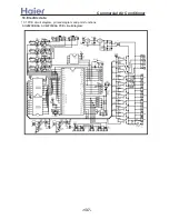
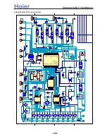
Page 138: ... a__WcU S c a V e a Wc AU282XHBAA AU422XIBAA PCB printed diagram 138 ...

Page 139: ... connected with the middle wire it is compulsory cooling CN15 time shorting port used to shorten 1 60 time CN16 serial port output used to connect the device CN17 system B low pressure switch wire CN18 system A high pressure switch wire CN19 system B high pressure switch wire CN22 system A low pressure switch wire CN23 to system B unloading valve CN24 transformer primary side input CN25 to indoor ...

Page 140: ... 1 2 2 3 3 4 4 5 5 6 6 7 7 8 8 9 9 10 10 11 11 12 12 13 13 14 14 15 15 16 16 IC3 2003 1 1 2 2 3 3 4 4 5 5 6 6 7 7 8 8 9 9 10 10 11 11 12 12 13 13 14 14 15 15 16 16 IC5 2003 RP2 103 D10 1N4148 R46 10K R48 1K R47 470 CTB 0057W RP1 103 D12 1N4148 R50 10K R59 1K R58 470 CTA 0057W 5V 12V R11 RJJ14 5 1K R12 RJJ14 5 1K R16 RJJ14 47K R14 RJJ14 47K 1 2 3 4 5 6 RA1 6P5R 472F 5v R60 5 1K R62 10K C13 4 7UF 16...

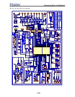
Page 141: ... a__WcU S c a V e a Wc AU84NXTBAA PCB printed diagram 141 ...

Page 142: ...e middle wire it is compulsory heating if the side marked with cool is connected with the middle wire it is compulsory cooling CN15 time shorting port CN16 serial port output used to connect the device CN17 system B low pressure switch wire CN18 system A high pressure switch wire CN19 system B high pressure switch wire CN22 system A low pressure switch wire CN23 to system B unloading valve CN24 tr...

Page 143: ... a__WcU S c a V e a Wc 1 2 3 4 5 6 7 8 10 11 12 13 14 15 16 9 IC1 2003 C32 104 1 P2 P6 187 E6 4 7uF IN OUT W1 7812 RL1 JQ1AP 1 RL3 JQ1AP A RL6 JQ1AP A AB AE AD units PCB circuit diagram 143 ...

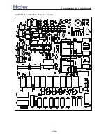
Page 144: ... a__WcU S c a V e a Wc AB AE AD units PCB printed diagram 144 ...

Page 145: ...trol signal neutral line N 0VAC CN1 input port of transformer 220VAC CN2 input port 1 of transformer no use CN3 input port 2 of transformer no use CN4 input port 3 of transformer 1 2 14VAC 3 4 12VAC CN5 input control connecting port to wired controller CONTROLLER three bits 1 power supply 12VAC 2 power supply 0VAC 3 communication COMM CN6 input control ambient temp coil temp sensor connecting port...

Page 146: ...h cuts off or occurs other failure LED1 will flash 10 times CN16 input control wiring port of central controller REMOTE 1 RS485 B 2 RS485 A CN17 output signal output signal of failure alarm control external load 12V ALM 1 control output 0VDC 2 power supply 12VDC CN18 output signal no use CN19 control external load swing 1 1 16VDC 2 0VDC 3 0VDC 4 0VDC 5 0VDC CN20 control external load swing 2 1 16V...

Page 147: ...3 IN4148 R11 10K C25 4 7U 50V R43 10K VCC R50 1K VCC C16 10UF C17 104 C12 100UF C11 104 R25 10K R22 10K VCC R23 10K R24 10K Q10 9013 Q9 9013 12 Q4 9014 Q8 9014 Q7 9014 R6 10K R4 560 R5 1K R3 5 1K VCC C20 103 R7 51K VCC C22 103 R8 51K IC4 P521 8 7 6 5 4 3 2 1 IC6 24LC01B LED4 VCC VCC VCC R18 10K R19 10K JK1 12V 220V 12 D2 IN4148 R1 2K R21 10K R20 10K R34 5 1K R35 5 1K 12 12 A0 A1 A2 VSS SDA SCL WP ...

Page 148: ...D8 1N4148 12V 5V ZERO IC2 P521 B2P3 VH LX1 15mH BP 1 S 2 S 3 EN 4 D 5 NC 6 S 7 S 8 IC1 TNY268P 1 2 CN101 R1 68K 2W NTC 5 0 R4 100K 2W R7 3K R5 10K 1 2 3 4 5 6 7 8 CN102 R3 1 5K Z1 11V D1 IN4007 D2 IN4007 D3 IN4007 D4 IN4007 Q1 9014 GND 5 R6 10K C7 470uF 25V GND 1 2 3 4 5 6 7 8 CN1 CON8 R1 10K R2 10K R3 10K R4 220 R5 220 R6 220 R7 10K Q1 9013 Q2 9013 Q3 9013 5 SW1 R8 10K R9 330 C2 4 7UF 50V OUT VCC...

Page 149: ... a__WcU S c a V e a Wc AF07 142XCBAA PCB printed diagram 149 ...

Page 150: ... sensor CN20 lower swing motor CN21 upper swing motor CN22 room card control connection port CN26 function selection input port CN27 connection port of remote receive board CN28 upper motor feedback signal input port Ports functions of filter board CN101 filter board power supply input port CN103 main control board power supply output port Ports functions of remote receive board SW1 emergency oper...

Page 151: ...1 K1 JQ1a 12V 5 R41 10K 2 TXD RXD C6 104 R22 1K R21 1K C23 102 C19 102 C18 102 5 1 2 3 4 5 6 7 8 9 10 11 12 13 14 15 16 IC5 2003 1 2 3 4 5 1 2 3 4 5 CN3 C D B A C D B A 12 12 12 5 C12 104 5 E4 2 2u 16V C8 104 5 C14 104 CN14 CN13 BZ1 R61 100 R56 4 7K 5 CN11 R4 10K P1 2SB1197K R46 470 R35 10k 5 P2 2SB1197K R47 470 R34 10k 5 P3 2SB1197K R48 470 R33 10k 5 12 R57 22K R14 4 7K 5 R18 1K 1 2 SW2 R27 1K R3...

Page 152: ...ort CN5 indoor ambient temp coil temp sensor port CN6 to central control detector CN8 time shorting port CN9 to realize network appliance function not available CN10 transformer secondary output CN11 transformer primary input CN12 fan motor connection port CN13 power supply neutral wire input port CN14 power supply live wire input port CN15 neutral wire of room card control CN16 live wire of room ...

Page 153: ...sor 1 R25 10KΩ 3 B25 50 3700K 3 2 R25 23KΩ 2 5 B25 50 4200K 3 AE072 142XCBAA 001A3900006 001A3900004 gas pipe temp sensor R25 10KΩ 3 B25 50 3700K 3 AB072 142XCBAA 001A3900006 001A3900004 gas pipe temp sensor R25 10KΩ 3 B25 50 3700K 3 model part No sub part No part name characteristic 0010450016 001A3800096 001A3800091 coil temperature sensor 1 R80 50KΩ 3 B25 80 4450K 3 2 R25 5KΩ 1 B25 50 3450K 1 0...

Page 154: ...36 3 99 04 41 11 22 2 19 39 42 2 432 2 93 52 42 10 76 1 18 39 43 2 339 1 88 35 43 10 31 0 17 45 44 2 25 0 83 5 44 9 89 1 16 55 45 2 165 1 78 94 45 9 49 2 15 7 46 2 084 2 74 67 46 9 1 3 14 89 47 2 006 3 70 65 47 8 74 4 14 13 48 1 932 4 66 88 48 8 39 5 13 41 49 1 862 5 63 33 49 8 05 6 12 73 50 1 793 6 60 50 7 73 7 12 08 51 1 729 7 56 86 51 7 43 8 11 47 52 1 667 8 53 91 52 7 14 9 10 9 53 1 608 9 51 1...

Page 155: ...29 64 55 3 22 8 2960 46 194 5 2 28 22 56 3 11 7 2793 47 186 3 3 26 4 57 3 11 6 2636 48 178 4 4 25 61 58 2 9 5 2489 49 170 9 5 24 41 59 2 81 4 2351 50 163 7 6 23 27 60 2 72 3 2221 51 155 9 7 22 2 61 2 63 2 2099 52 150 4 8 21 18 62 2 54 1 1984 53 144 2 9 20 21 63 2 49 0 1877 54 138 3 10 19 3 64 2 38 1 1775 55 132 7 11 18 43 65 2 3 2 1680 56 127 3 12 17 61 66 2 23 3 1590 57 122 1 13 16 83 67 2 16 4 1...

Page 156: ...2 Outdoor coil A temp sensor failure 3 Outdoor ambient temp sensor failure 4 Air outlet A temp sensor failure 5 Outdoor coil B temp sensor failure 6 Air outlet B temp sensor failure 7 Discharging B pipe temp too high 9 Low pressure malfunction 10 Communication failure between indoor and outdoor 11 Overcurrent protection 13 High pressure malfunction 15 EEPROM failure 156 ...

Page 157: ...ing LED flashes twice Communication between indoor and outdoor abnormal E3 Running LED flashes 3 times Compressor overheat E4 Running LED flashes 4 times CT current abnormal E5 Running LED flashes 5 times Outdoor ambient temp sensor abnormal E6 Running LED flashes 6 times Outdoor coil pipe temp sensor abnormal E7 Running LED flashes 7 times Outdoor suction temp sensor abnormal EA Running LED flash...

Page 158: ...ore than 2m continuously 4 73 49H 12D Outdoor coil temp sensor failure compressor discharging temp sensor Sensor broken down or short circuit for more than 2m continuously 5 72 48H 10D Over current protection CT check abnormal 3 times in 30m 6 83 53H 14D High pressure abnormal High pressure switch acts 3 times in 30m 7 71 47H 22D Power supply abnormal Fault phase short of phase out of balance grea...

Page 159: ...w pressure switch acts in normal running 17 80 50H 15D Compressor overheat the discharging temperature is higher than 120degree Resumable if lower than 100degree 18 12 0CH 23D Abnormal mode Indoor operation mode is different with the running indoor unit 19 75 4BH 18D Outdoor coil B suction temp sensor for MRV II Sensor broken down or short circuit for more than 2m continuously 20 77 4DH 15D Outdoo...

Page 160: ...temperature setting correct e g too high 3 Is system in TIMER mode 4 Is user aware of product features etc Check the system thoroughly e g technical data of components when power off and voltage and current of check points when power on Disconnect contactor and reconnect it check if fuse or varistor is broken Does the same fault occur before Switch off air conditioner temporarily Switch on air con...

Page 161: ...rt circuit or open circuit Replace sensor Is sensor resistance acceptable Replace sensor Is DC voltage between both ends of sensor near 5V or 0V Replace PCB yes yes yes yes no no no replace EEPROM start re set 3 EEPROM failure Is EEPROM in mainboard inversely connected or in poor contact no Power on again to check if failure is eliminated no replace PCB 161 ...

Page 162: ...ns no yes change defective parts re wiring Confirm commumication failure according to the fault code list 4 Communication error between indoor and outdoor units yes yes S should not share a multicore cable with L and N no no no no no yes yes yes re wiring Confirm the failure according to the fault code list yes no yes There is short time fault readout It s normal Fault readout disappears after a w...

Page 163: ...rigerant leak If yes replace pipe yes is pipe blocked no Is high pressure too low yes yes high pressure failure no low pressure failure no yes Is actual pressure detected by pressure gage acceptable yes yes Replace PCB no Are ports in PCB cut off Does system have pressure switch Confirm the fault according to the fault code list 7 Pressure protection Note The confirmation time of low pressure fail...

Page 164: ... no repair or replace yes Is piping twisted or deformed no cleaning Is filter or heat exchanger dirty yes yes no no Does indoor fan motor work properly in heating cycle Does outdoor fan motor work properly in cooling cycle replace PCB Air conditioner is running in bad condition Unclog piping If the pipe is blocked Are they too low Are high pressure and low pressure normal replace PCB yes yes yes y...

Page 165: ...essure switch yes if outdoor stop valves of gas pipe and liquid pipe are open totally no Open the valves yes Is piping twisted or deformed yes Repair pipe no Does indoor fan work properly during cooling cycle Does outdoor fan work properly during heating cycle no Repair fan motor or fan capacitor yes Is indoor filter or heat exchanger dirty yes Cleaning no Measure equalized pressure and time to re...

Page 166: ...zed pressure in halt yes Evacuate and recharge no Is reading of discharging pressure gage oscillatory no Bad operation codition such as ultra low outdoor temperature yes There is air in system Evacuate and recharge 10 High pressure protection Confirm the fault according to the fault code list yes Check and reconnect no Are connectors of pressure switch in good condition Is high side pressure switc...

Page 167: ...or that interference arises yes Adjust holder no yes Replace float switch no Replace indoor PCB Note Float switch is close in normal state when being activated it is open Voltage between both ends is 0V when close approximately 5V when open Unclog pipe and water pump Is drain pan dirty and float switch ineffective Is pump motor in good condition Is drain pipe clogged yes Check if float switch is i...

Page 168: ...ly located Is resistance of indoor sensor correct Does four way valve work properly Relocate Replace four way valve Is outdoor four way valve in good condition during heating cycle Does small relay coil of four way valve have a voltage of 12V DC no Relay is broken Replace PCB Is indoor unit malfunction caused by lack of refrigerant charge refrigerant Is heat exchange effect adversely affected by h...

Page 169: ... Check other possible causes E g motor is stuck Replace fan capacitor Replace PCB No It s split winding type motor Is it a PG motor As in AS and AF indoor units Is output voltage good when energized Does fan motor run properly Is there DC voltage feedback from motor during running Signal detecting circuit has a problem Replace PCB Replace motor Is front end voltage of thyristor good Supply circuit...

Page 170: ...3 6 3 8 3 9 27 19 2 9 3 0 3 0 3 3 3 4 3 6 3 8 4 0 30 22 2 9 3 1 3 1 3 4 3 5 3 8 3 9 4 1 32 23 3 0 3 1 3 1 3 4 3 6 3 8 4 0 4 2 Power consumption chart kW change with the temperature AU282XHBAA Outdoor temp Outdoor temp Cooling capacity chart kW change with the temperature AU282XHBAA AU222XHBAA AU282XHBAA AU302CHBAA 5 2 5 0 2 5 5 0 5 7 5 10 12 5 15 100 98 96 94 92 Equivalent total distance between i...

Page 171: ...46 27 19 9044 8792 9638 8267 8149 7477 7232 6986 30 22 10058 9780 9710 9234 8920 8329 8192 7691 32 23 10287 10114 10027 9400 9253 8592 8394 7992 32 24 10660 10464 10419 9752 9565 8879 8641 8273 outdoor temp humidity 46 cooling capacity temperature table AU282XHBAA AE142XCBAA 2 performance curves cooling capacity temperature curves 4000 5000 6000 7000 8000 9000 10000 11000 18 12 18 14 20 15 22 16 2...

Page 172: ...29 3582 3741 3914 27 19 2840 2932 2943 3241 3363 3609 3793 3970 30 22 2966 3064 3070 3348 3480 3748 3918 4106 32 23 3024 3114 3111 3391 3520 3801 3973 4173 32 24 3071 3162 3150 3428 3563 3843 4021 4214 power consumption temp table outdoor temp humidity 46 AU282XHBAA AE142XCBAA 2 performance curves power consumption temp curves 2000 2500 3000 3500 4000 4500 18 12 18 14 20 15 22 16 25 18 27 19 30 22...

Page 173: ...85 14 98 15 25 27 19 14 74 14 91 14 02 15 37 15 53 16 07 16 25 16 45 30 22 17 64 17 8 17 79 18 23 18 48 18 87 19 95 19 22 32 23 18 81 18 95 19 01 19 52 19 65 20 14 20 2 20 5 32 24 18 32 19 8 19 82 20 31 20 42 20 9 20 97 21 23 air outlet temp ambient temp table outdoor temp humidity 46 AU282XHBAA AE142XCBAA 2 performance curves air outlet temp ambient temp curves 5 7 9 11 13 15 17 19 21 18 12 18 14...

Page 174: ...9 7139 7042 7250 6816 6727 6429 6259 6135 30 22 7158 7023 6847 6870 6725 6496 6412 6216 32 23 7614 7541 7482 7267 7195 6919 6800 6623 32 24 7142 7059 7017 6812 6743 6476 6374 6209 sensible cooling value temperature table outdoor temp humidity 46 AU282XHBAA AE142XCBAA 2 performance curves sensible cooling value temp curves 4000 4500 5000 5500 6000 6500 7000 7500 8000 18 12 18 14 20 15 22 16 25 18 2...

Page 175: ... 4 6 indoor D B W B power consumption kW 18 14 20 15 22 16 25 18 27 19 30 22 32 23 The data is measured in the normal condition outdoor DB WB 35 24 indoor DB WB 27 19 High drop and long pipe capacity modification curves AU422XIBAA 15 12 5 10 7 5 5 2 5 0 2 5 5 7 5 10 0 5 7 5 10 12 5 15 17 5 20 100 88 98 96 94 92 90 Equivalent total distance between indoor and outdoor unit of one way m The standard ...

Page 176: ...0 12 20 14 5 27 18 heating capacity and indoor outdoor temp curves AU42 9000 11000 13000 15000 17000 19000 5 0 5 7 6 10 15 24 outdoor temp heating capacity W 20 15 20 12 20 14 5 27 18 heating capacity and indoor outdoor temp curves AU84 20000 25000 30000 35000 40000 5 0 5 7 6 10 15 24 outdoor temp heating capacity W 20 15 20 12 20 14 5 27 18 12 3 Heating performance curves 176 ...

Page 177: ... 15 24 Heating power input indoor outdoor temp curves AU422XIBAA 2500 3500 4500 5500 6500 7500 8500 9500 10500 11500 12500 13500 14500 15 10 18 13 20 14 5 27 18 indoor temperature DB WB power input W 5 0 5 7 6 10 15 24 Heating power input indoor outdoor temp curves AU84NXTBAA 8000 9000 10000 11000 12000 13000 14000 15 10 18 13 20 14 5 27 18 indoor temperature DB WB power input W 5 0 5 7 6 10 15 24...

Page 178: ...a Air volume m3 h super high high med low Air volume and external static pressure curves AE122XCBAA AE142XCBAA 0 200 400 600 800 1000 3 0 P a 2 5 P a 2 0 P a 1 5 P a 1 0 P a 5 P a 0 P a External static pressure Pa Air volume m3 h super high high med low Air volume and external static pressure curves AE122XCBAA AE142XCBAA 0 200 400 600 800 1000 1200 30Pa 25Pa 20Pa 15Pa 10Pa 5Pa 0Pa External static ...

Page 179: ...D 7FM CGJQ 6 HH7L 00 02 03 8 7 6 5 4 2 3 2 3 4 5 6 7 8 GJQBM GFHFO PKKBM GFHFO a__WcU S c a V e a Wc AD282XHBAA 0 0 3 3 3 3 04 1 ST 13 2 O IA MA 6FM CGJQ H HFI 3 PONFAB NO OF KMBNNPMB HH6L 8R HKGB JC AP O 7JIAFOFJI JC NO IA MA M OFID 6FM CGJQ 5 HH6L 21 8 7 6 5 4 3 2 8 7 6 5 4 3 2 9FDE JQ JQBM GFHFO KKBM GFHFO AD422XHBAA 179 ...

Page 180: ...MEMO Commercial Air Conditioner ...

Page 181: ...No 1 Haier Road 266001 Qingdao China Tel 86 532 8939486 9711 Fax 86 532 8939715 E mail cactech haier com Http www haier com All rights reserved and the information in this manual is subject to change without notice in order to make the information keep latest ...

Reviews: