

8.2 Electric funtions of outdoor
8.2.1 Control of the compressor, outdoor motor and 4-way valve
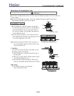
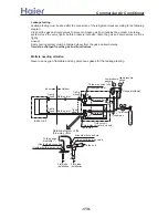
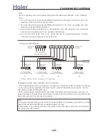
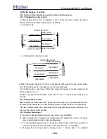
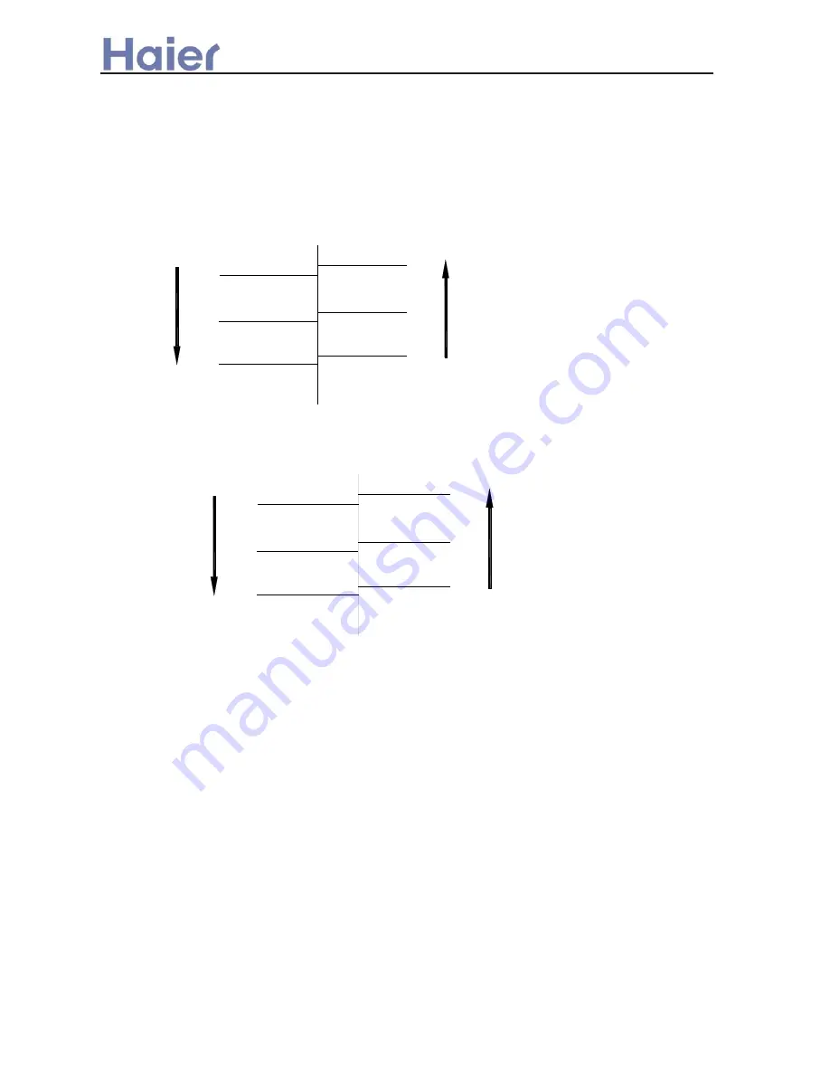
8.2.1.1 Outdoor fan motor control
A. When system do not have overheating or over current protection, outdoor fan speed
will vary with outdoor ambient temperature, as follows:
a. in cooling mode
te
mp
era
tur
e a
ris
e
super low speed
low speed
med speed
high speed
super low speed
low speed
med speed
high speed
15
℃
24
℃
28
℃
13
℃
22
℃
26
℃
te
mp
er
at
u
re reduce
outdoor fan motor
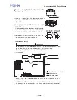
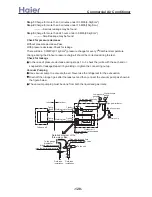
b.
in heating mode (heat pump unit)
te
m
pe
rat
u
re aris
e
super low speed
low speed
med speed
high speed
11
℃
19
℃
9
℃
16
℃
temper
atur
e r
ed
uc
e
outdoor fan motor
super low speed
low speed
med speed
high speed
22
℃
23
℃
B.When fan speed changes, if it is from Low speed to High speed, there is no time delay;
if it is from High speed to Low speed, there is 45-second delay.
C.In cooling mode, in one minute before the compressor begins to run,the outdoor motor
will be switched on to run.
D.Super low speed control:outdoor motor will be off for 1 minute at the interval of 45
seconds.
8.2.1.2 Compressor control
After receiving the “compressor ON” signal sent from indoor unit, the compressor will run.
Its running-stop interval is 3 minutes. Being powered on firstly is without 3-minute delay.
If the two systems receive the “compressor ON” signal simultaneously,they will start up in
turn, and the interval is 20 seconds.
8.2.1.3 4-way valve control
A. In cooling or dehumidification mode, 4-way valve is not electrified.
B. When receiving the “heating” and “compressor ON” signal from indoor unit, 4-way
valve and compressor will start up simultaneously.
C. In 3 minutes after heating is over, it will be shut off 2 minutes and 50 seconds later. In
3-minute standby period, at 2-minute and 50-second clock, it is electrified.
D. Changing from cooling mode to heating mode, 3 minutes later, it is eletrified.
>a__WcU[S^ <[c >a`V[e[a`Wc
-129-
Summary of Contents for AB072XCBAA
Page 21: ... a__WcU S c a V e a Wc AU84NXTBAA 66 33 1 23 4 43 33 61 2 3 160 2 15 3 52 21 ...
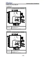
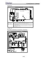
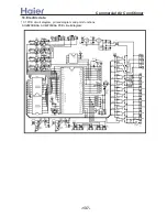
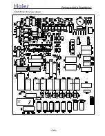
Page 138: ... a__WcU S c a V e a Wc AU282XHBAA AU422XIBAA PCB printed diagram 138 ...
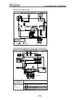
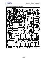
Page 141: ... a__WcU S c a V e a Wc AU84NXTBAA PCB printed diagram 141 ...
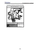
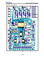
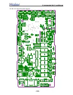
Page 144: ... a__WcU S c a V e a Wc AB AE AD units PCB printed diagram 144 ...
Page 149: ... a__WcU S c a V e a Wc AF07 142XCBAA PCB printed diagram 149 ...
Page 180: ...MEMO Commercial Air Conditioner ...


