

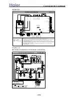
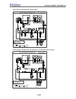
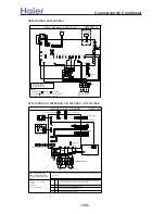
>a__WcU[S^ <[c >a`V[e[a`Wc
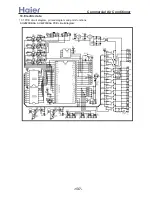
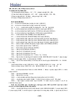
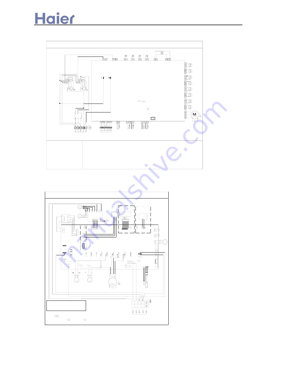
AU84NXTBAA:
0010575119
Transformer
3
Valve B
CN12
1
2
3
2
Valve B
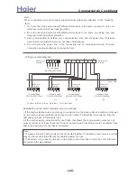
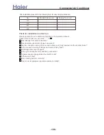
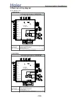
Outdoor wiring diagram
CN17
2
CTA
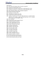
Note:
1.Communicaton terminal block connected to indoor can not be high voltage, or the PCB will be burned.
2.After powered on,the communication lamp on the PCB can not flash normally,that shows the communication wire between indoor
and outdoor is wrong.Please check the wiring carefully and change the wiring sequence of communication wires until the
communication lamp flashes normally.
3.If the "NORMAL" lamp (green) on the 3-phase detecting board is on,which shows the power wiring is right.If the "ERR" lamp (red)
is on,which shows the power wiring is wrong.The wiring of L1,L2,L3 need to be changed.Pay attention that "N" must be connected
to the neutral wire or PCB will be damaged.
4.Port 1,2 of CN14 is in short circuit,outdoor unit will enter compulsory cooling mode.Port 2,3 is in short circuit,it will enter
compulsory heating mode.
5.For different outdoor units,the heater is optional.
D
efros
ting T
em
p
Sens
or
A
Control PCB
W:White BR:Brown
B:Black BL:Blue
R:Red Y/G:Yellow/Green
R
BL
W
To Indoor Unit
Power Supply
Y/G
Am
bi
en
t T
e
m
p.
Sen
sor
Dis
ch
a
rg
in
g T
em
p
Se
ns
or
B
D
e
fr
osti
ng
T
e
m
p
Sens
or
B
CN6
B
B
COM
N.O
Capacitor
D
is
char
gi
ng
T
em
p
Se
ns
or
A
Valve A2
Fan Motor
Valve A1
CN9
LE3
CN14
ERR
1
CN4
2
1 2 1
2 3
C
OOL
HE
AT
CTB
1
H
2
M
5
COM
L
4
3
2
1
3
3
CN25
1
2
CN26
CN23
1
Hi
g
h Pr
essu
re
Sw
itc
h B
4-Way
Valve A
Valve B2
Unloading Solenoid
Valve B1
CN29
CN28
1
2
3
2
1
CN27
3
CN11
1
2
3
Valve A
1
2
3
4-Way
Unloading Solenoid
CN19
CN8
CN24
2
1
1 2
2 3
1
R
T
S
W BL
R
B
1
3
2
BR
R
2
1
CN2
4
CN1
1
3 4
2
1
CN3
3
2
4
B
BR
Compressor A
R
BL
W
R
C
o
mp
re
ssor A
Co
m
pr
esso
r B
Hi
g
h Pr
essu
re
Sw
itc
h A
BL
BR
R
W
BL
W R
M
M
Compressor B
CTB
CTA
BL
1
CN33
CN32
CN22
CN18
Lo
w
Pr
es
su
re
Sw
itc
h A
Lo
w
Pr
es
su
re
Sw
itc
h B
3
2
2
1
3
2
1
1 2
1
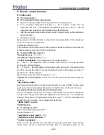
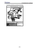
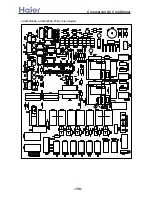
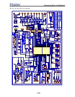
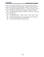
9.2 Indoor unit
AB072XCBAA, AB092XCBAA, AB122XCBAA, AB142XCBAA:
1 2
NOTE:
1. Parts in dashed frames are factory optional .
3. P16 and P17 are used for room card function
2. Central controller and fresh air are optional.
3
4
POWER
SUPPLY
TO
OUTDOOR
UNIT
CIRCUIT DIAGRAM OF INDOOR UNIT
0010573646
(L
)
(N')
(C
O
MM)
(M
)
(H
)
P17
(H
U
M
I)
(H
E
A
T)
(P
U
M
P
)
T3
.1
5A
/2
50
V
A
C
FAN MOTOR
Y:Yellow OR:Orange
R:Red Y/G:Yellow/Green
BL:Blue BR:Brown
W:White B:Black
B
W
B
W
MOTOR
SWING
M
MOTOR
PUMP
M
P5(N3)
P2(N)
P1(L)
P6(N4)
SENSOR
ROOM
Y/G
L
Q
P
2
1
3
N
4
FAN CAP.
SENSOR
TEMP.
W
B
(ROOM/PIPE)
Y/G
M
W
B
CN23
CN10
CN22
CN6
PIPING TEMP.
3
24
1
2
3
SW3
ON
23
4
1
SW1
ON
1
SW2
ON
(UP-DOWN)
CN7
FU
SE
P4(N2)
(FR
E
S
H
)
P3(N1)
P8
P9
P7
P10
4
CN5
CO
NTRO
LL
E
R
)
CN14
1
5
4
2
3
6 1
FILTER
MOTOR
M
FILTER PCB
MC1
COM
MC2
CN2
N FG
CN1
L
M
R
BL
B
B
W
(A
LA
R
M
)
CN12
P14
P13
P11
P12
(L')
P15
P16
CN13
RECEIVE BOARD
B
2
3
A
(REMOTE)
CN16
(F
LO
A
T
)
2
1
ON
34
SW5
CN21
2
1
SW4
ON
4
CN11
CN15
SWITCH
(D
OOR
)
FLOAT
CONTROLLER
CENTRALIZED
P
CONTROLLER
REMOTE
RECEIVER
WIRED
CONTROLLER
REMOTE
(O
XY
G
E
N
)
R
(S
W
IN
G
)
CN1
TRANS.
CN4
-133-
Summary of Contents for AB072XCBAA
Page 21: ... a__WcU S c a V e a Wc AU84NXTBAA 66 33 1 23 4 43 33 61 2 3 160 2 15 3 52 21 ...
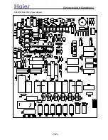
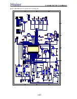
Page 138: ... a__WcU S c a V e a Wc AU282XHBAA AU422XIBAA PCB printed diagram 138 ...
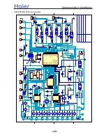
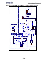
Page 141: ... a__WcU S c a V e a Wc AU84NXTBAA PCB printed diagram 141 ...
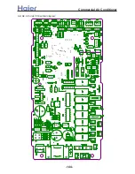
Page 144: ... a__WcU S c a V e a Wc AB AE AD units PCB printed diagram 144 ...
Page 149: ... a__WcU S c a V e a Wc AF07 142XCBAA PCB printed diagram 149 ...
Page 180: ...MEMO Commercial Air Conditioner ...


