

Threads on the pipes may be damaged
when tightening if the pipes are not
well aligned.
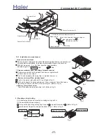
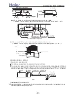
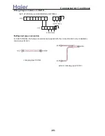
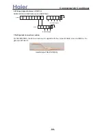
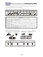
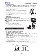
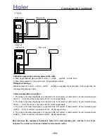
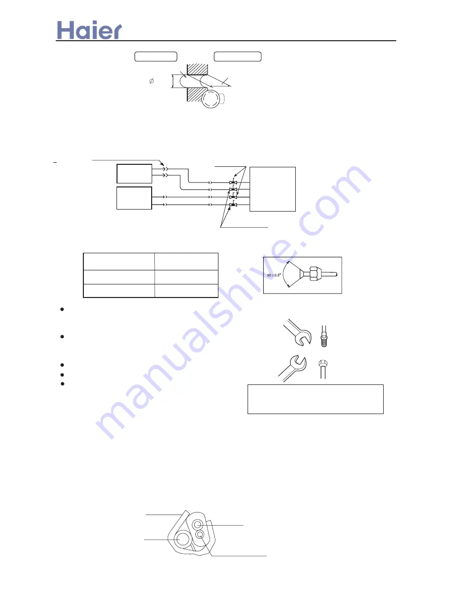
(1)Schematic diagram for unit connection
(4)
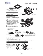
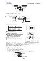
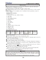
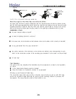
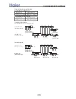
Pipe connection process
Torque
18 N.m
Pipe Value
6.35mm
50 N.m
(2) Connection pipe dimensions:
12.7mm
Outdoor uint
3-way Valve
2-way Valve
Indoor unit
Indoor unit
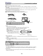
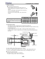
Apply and tighten the nut.
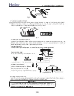
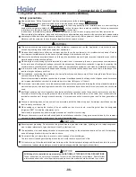
(3)Cautions for pipe connection
Pipes free from twists, deformation, water, dust.
Dedicated tools for each R407C and R22
should be used and stored separately.
Optimized radii of bends
Insulation to be applied on all gaseous pipes
Flared section free from cracks
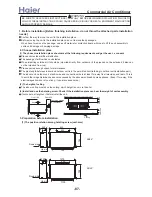
Joint
Spanner
Spanner
Nut
Apply refrigeration oil on the end of the pipe to be connected and on the flared section.
Align the pipes to be connected and tighten the nut. (See the figure)
Ensure that no foreign articles enter into the pipes.
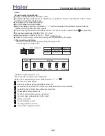
Flared pipe connection
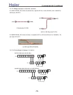
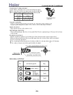
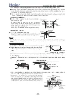
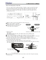
Liquid
Gas
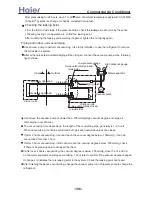
Indoor side
Outdoor side
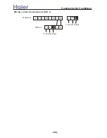
Thickness
of wall
Wall hole
70mm
(Cross section of wall hole)
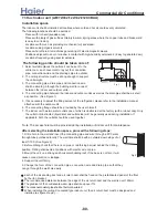
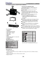
Piping connection of the indoor unit
1. Arrangement of piping and drainage pipe
After opening inlet grill,you will see a control box.
Remove the cover before working.
Cut away, with a hammer or a saw, the lid for piping according to piping direction.
Insulation material
Copper tube
Drain hose
Connecting electric cable
for indoor and outdoor unit
>a__WcU[S^ <[c >a`V[e[a`Wc
-91-
Summary of Contents for AB072XCBAA
Page 21: ... a__WcU S c a V e a Wc AU84NXTBAA 66 33 1 23 4 43 33 61 2 3 160 2 15 3 52 21 ...
Page 138: ... a__WcU S c a V e a Wc AU282XHBAA AU422XIBAA PCB printed diagram 138 ...
Page 141: ... a__WcU S c a V e a Wc AU84NXTBAA PCB printed diagram 141 ...
Page 144: ... a__WcU S c a V e a Wc AB AE AD units PCB printed diagram 144 ...
Page 149: ... a__WcU S c a V e a Wc AF07 142XCBAA PCB printed diagram 149 ...
Page 180: ...MEMO Commercial Air Conditioner ...


