26
Installation procedure
Install wire controller
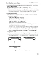
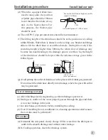
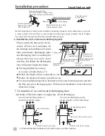
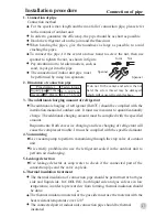
1.Remove the upper cover of wire controller
2.Install wire controller
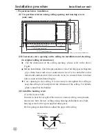
Drill 2 wall holes according to the position of the 2 screw holes on the back cover
of wire controller, then hit wood in the wall holes. Put the 2 screw holes on the
back cover of wire controller properly to its corresponding wood, then use wood
screws to fix the back cover on the wall.
Note:
Install the back cover of wire controller on the even wall as possible as can.
When tightening the wood screw, do not use to tight force, otherwise the wire
controller may be damaged.
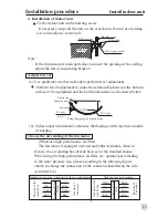
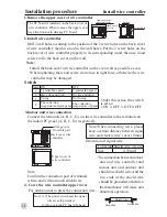
Switch
Under this series, the switch
is set as:
1.ON 2. OFF 3. OFF 4.OFF
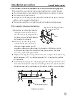
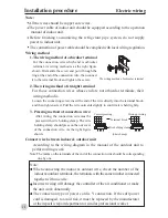
3.Indoor unit wire connection
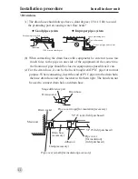
Connect the terminals (A, B, C, D,) on the wire controller to the terminals on
the indoor PC panel (A, B, C, D,) respectively.
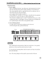
Dimension of signal wire:
*
The connection between indoor
unit and wire controller and
indoor unit and outdoor unit
should use shield wire.And the
two ends of the shield wire
should be grounded, otherwise,
the disturbance will cause unit
abnormal operation.
Note:When connecting wire, please
keep a certain distance between signal
wire and electric wire. (over 10mm)
4. Cover the wire controller upper cover
Pay attention not to press the connection wire.
Note: (1) The power switch and the signal
wire are self-provided.
(2) Do not touch PC board by hand.
Note:
Confirm the connection part of terminals
is firm and will not touch shield wire.
Grounded
Shield wire
Grounded
Mark
1
2
3
ON
3 grades fan speed
Have rise and drop
Swing
OFF
2 grades fan speed
No rise and drop
Not Swing
4
The collection
temperature of main panel
The collection
temperature of panel
Back cover wire
controller
Arrange wire
from this part
AB CD
Upper cover of
wire controller
The PC board is installed on the back cover of
wire controller. When remove the upper cover,
pay attention not to damage PC board.
Screw hole
Switch
Upper cover of
wire controller
Back cover
of wire
controller
Cord kind Shield wire (4 core)
Size
0.33mm
2


