background image

INSTALLATION MANUAL FOR INDOOR UNIT

31

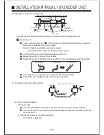
Exhaust hole

State seeing from top of unit

Side fresh air inlet

Rear fresh air inlet

Fig.1

Fig.2

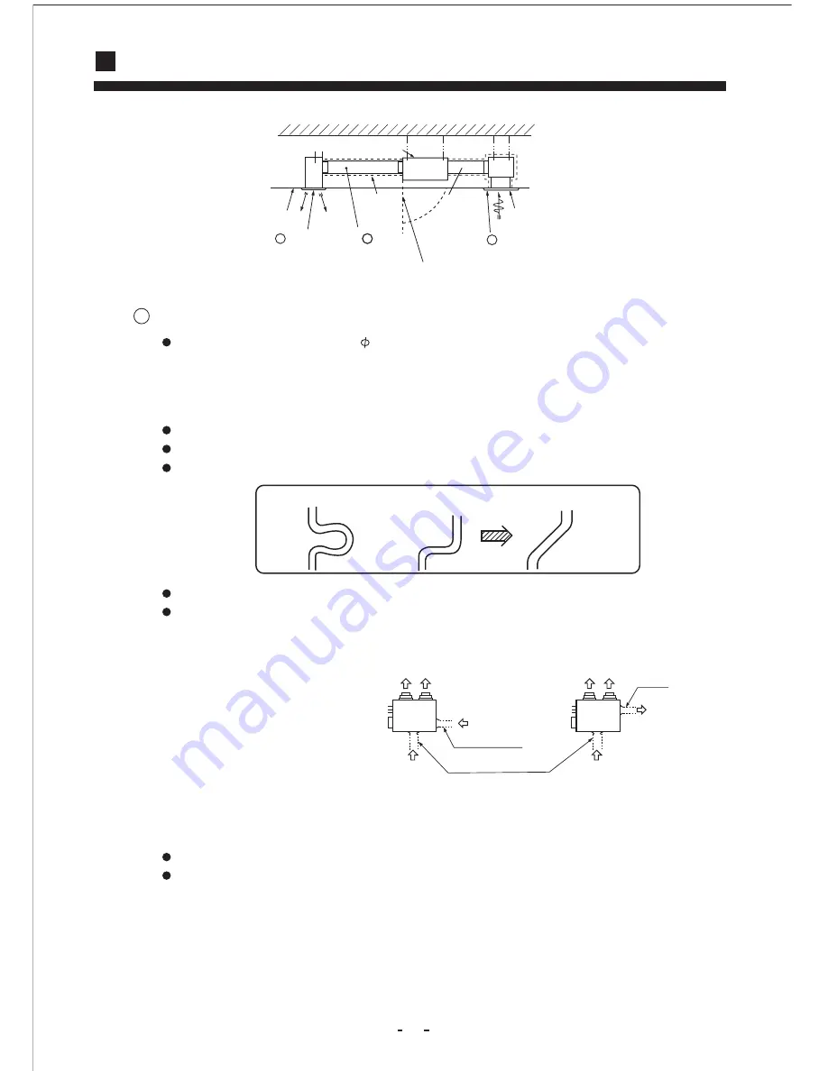
(7)  Installation work for air outlet ducts

Calculate the draft and external static pressure and select the length, shape and blowout.

   Blowout duct

2-spot, 3-spot and 4-spot with     200 type duct are the standard specifications. Determine
the number of spots based on following table.

Note  (1) Shield the central blowout hole for 2-spot.
          (2) Shield the blowout hole around the center for 3-spot.

Limit the difference in length between spots at less than 2:1.
Reduce the length of duct as much as possible.
Reduce the number of bends as much as possible. (Corner R should be as larger as possible.)

Use a band. etc. to connect the main unit and the blowout duct flange.
Conduct the duct installation work before finishing the ceiling.

(8)  Connection of suction, exhaust ducts

(a) Duct connection position

i) Fresh air inlet

Inlet can be selected from the side or rear faces depending on the working conditions.
Use the rear fresh air inlet when the simultaneous intake and exhaust is conducted. (Side inlet
cannot be used.)

ii) Exhaust (Make sure to use also the suction.)

Use the side exhaust port.

Good example

Bad example

Bad example

Ceiling surface

Heat

insulation

Suction panel

(Silent panel)

Air conditioner main unit

B  Special blowout

     (Option)

A  Blowout duct

     (Optional or marketed item)

C

Hole for check

special inlet (option)
(with air filter)

inlet duct

 (optional or

 marketat item)

Summary of Contents for AD242AMBAC

Page 1: ... HDU 24CL03 M R1 AD28NAMNAC AU28NANNAC HDU 28CM03 M R1 AD36NAMNAC AU36NAPNAC HDU 36CM03 M R1 AD42NAMNAC AU42NAPNAC HDU 42CM03 M R1 AD242AMBAC AU242ANBAC HDU 24HL03 M R1 AD28NAMBAC AU28NANBAC HDU 28HL03 M R1 AD36NAMBAC AU36NAPBAC HDU 36HM03 M R1 AD42NAMBAC AU42NAPBAC HDU 42HM03 M R1 ...

Page 2: ...INTENANCE 17 FOR PREPARATION OF HEATING 18 IS THE UNIT INSTALLED CORRECTLY 19 INSTALLATION MANUAL FOR WIRE CONTROLLER 20 21 INSTALLATION MANUAL FOR OUTDOOR UNIT 22 25 INSTALLATION MANUAL FOR INDOOR UNIT 26 31 SAFETY PRECAUTIONS 3 5 PARTS AND FUNCTIONS 6 8 CAUTIONS 2 ...

Page 3: ... an appropriate anti pollution method of disposal Disposal of the packaging of your new air conditioner All the packaging materials employed in the package of your new air conditioner may be disposed without any danger to the environment The cardboard box may be broken or cut into smaller pieces and given to a waste paper disposal service The wrapping bag made of polyethylene and the polyethylene ...

Page 4: ...cident by some improper handing Do not install nearby the place where may have leakage of flammable gas Depending on the place of installation a circuit breaker may be necessary Drain pipe should be arranged to provide a positive draining If the gas leakes and gathers around it may cause the fire Unless the circuit breaker is installed it could cause elecrical shocks Where strong winds may prevail...

Page 5: ...injury If the system is operated at the vicinity of such equip ment which generates steam condensed water may drip during cooling operation or it could cause a fault current or short circuit When operating the system simultaneously with a combustion apparatus indoor air must be ventilated frequently Check occasionally the support structure of the unit for any damage after a use of long period of t...

Page 6: ...r 24 28 series 1PH 220 230V 50Hz the connecting cable should be H05RN F 4G0 75mm2 All the cables shall have got the European authentication certificate During installa tion when the connecting cables break off it must be assured that the grouding wire is the last one to be broken off 6 The breaker of the air conditioner should be all pole switch and the distance between its two contacts should be ...

Page 7: ...et Air inlet Duct Air outlet Air inlet Duct Outdoor Unit Air inlet Air outlet Compressor Inside of unit Connecting piping and electrical wiring Air inlet Air outlet Drain hose For series 24 28 For series 36 42 For series 24 28 For series 36 42 ...

Page 8: ... select TIMER ON TIMER OFF TIMER ON OFF TIME Used to set clock and timer setting Used for unit start and stop Power ON OFF MODE Used to select AUTO RUN COOL DRY HEAT and FAN operation FAN SPEED Used to select fan speed LO MID HI AUTO TEMP Used to select your desired temp SET Used to confirm Timer and Clock settings SLEEP Used to select sleep mode AM PM AM PM C PARTS AND FUNCTIONS Operation AUTO SE...

Page 9: ...should be adjusted as follows Press CLOCK button AM or PM flashes Press or to set correct time Each press will increase or decrease 1min If the button is kept depressed time will change quickly After time setting is confirmed press SET AM and PM stop flashing while clock starts working Operation Remote control AM PM AM PM C AUTO SET ROOM O N O F F MODE FAN SWING TEMP CLOCK SET TIMER SLEEP RESET FI...

Page 10: ...selected mode stop display at FAN Press FAN button For each press fan speed changes as follows Unit will run at selected fan speed Wire controller can memorize settings in each operation mode To run it next time just select the operation mode and it will start with the previous setting No reselecting is needed TIMER ON OFF needs reselecting In FAN mode temp can t be set Hints For cooling only type...

Page 11: ...ase quickly Recommendations Hints Wire controller can memorize each operation status When starting it next time just press ON OFF button and unit will run in previous status Press FAN button For each press fan speed changes as follows 4 Fan speed selection Unit runs at the speed displayed on LCD In HEAT mode warm air will blow out after a short period of time due to cold draft prevention function ...

Page 12: ...ress TIME button Every time the button is pressed time increases 10 min If button is kept depressed time will change quickly Every time the button is pressed time decreases 10 min If button is kept depressed time will change quickly Time will be shown on LCD It can be adjusted within 24 hours 4 Confirming your setting After setting correct time press SET button to confirm ON or OFF stops flashing ...

Page 13: ...on is kept depressed time will change quickly Time will be shown on LCD It can be adjusted within 24 hours AM refers to morning and PM to afternoon Time displayed Unit starts at X hour X min After time setting press TIMER button to confirm ON stops blinking While OFF starts blinking 4 Time confirming for TIMER ON Follow the same procedures in Time setting for TIMER ON 6 Time confirming for TIMER O...

Page 14: ...P RUN STOPS 1 hr 1 hr 3 hrs about 3 hrs decrease 2 C decreases 2 C increase1 C SHUT DOWN SLEEP RUN STOPS Heat mode SLEEP RUN BEGINS SETTING T SHUT DOWN Cooling mode Comfortable Sleep Note In AUTO mode unit will run in SLEEP function according to the operation mode After setting SLEEP function it is forbidden to calibrate clock If the set sleep time does not reach 8 hours the unit will stop operati...

Page 15: ...he air conditioner will enter the state of power failure compensation Cancel Method Press the Sleeping button on the wire controller 10 times within 5 seconds and after the buzzer rings 2 timer the power failure compensation mode will be cancelled Notes When a power failure suddenly occurs during the air conditioner is working after the power failure compensation is set if the air conditioner will...

Page 16: ...loor The wind does not blow during heating operation Isn t it warming up page 9 When the air conditioner does not operate properly after you have checked the above mentioned items or when the following phenomenon is observed stop the operation of the air conditioner and contact your sales dealer The fuse or breaker often shuts down Water drops off during cooling operation There is a irregularity i...

Page 17: ...itched into the FAN mode during cooling To prevent frost from being accumulated on the indoor unit heat exchanger it is sometimes automatically switched to the FAN mode but it will soon return to the cooling mode Even if the operation switch is turned on cooling dehumidifying or heating is not operable for three minutes after the conditioner is stopped Because the protecting circuit is activated D...

Page 18: ... Do not open the inlet grill until fan stops completely Fan will continue rotating for a while by the law of inertia after operation is being stopped CAUTION Pre Season Care See that there are no obstacles blocking the air inlet and air outlet of both indoor and outdoor units Make sure that the air filter is not dirty Cut in the power supply switch 12 hours before starting run Post Season Care Ope...

Page 19: ...over to ordinary heating operation WARMING OPERATION Heat pump type warming Defrosting operation Atmospheric temperature and warming capacity Period of warm up With the heat pump type warming the mechanism of heat pump that concentrate heat of outdoor air with the help of refrigerant to warm the indoor space is utilized When a room is warmed with a heat pump type air conditioner frost accumulates ...

Page 20: ...gas generates Hot spring area etc The place where salt breeze blows Seaside etc The place where dense soot smoke exists The place where humidity is extraordina rily high The place where near the machine which radiates the electromagnetic wave The place where voltage variation is con siderably large For details consult your sales dealer The electric work must be burden on the authorized engineer wi...

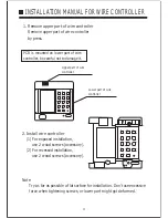
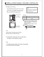
Page 21: ...tallation use 2 wood screws accessory 2 For recessed installation use 2 wood screws accessory Note Try as far as possible a flat surface for installation Don t use excessive force when tightening screws or lower part might got deformed PCB is mounted on lower part of wire controller be careful not to damage it Lower part of wire controller Upper part of wire controller ...

Page 22: ...ze Shield wire 4 core refer to Hint 3 4 0 33mm2 Wire size 4 Replace the upper part of wire controller Hint Be careful not to press the wiring 1 Switch box and cord for wiring are not supplied 2 Don t touch PCB with hand Use shielede wires for telecommunication between wire controller and indoor unit indoor unit and outdoor unit Ground the shield on one side Otherwise misoperation because of noise ...

Page 23: ...erhead space is needed for the unit Mount guide louvers to place where short circuit is a possibility When installing several units secure sufficient suction space to avoid short circuiting Heat Pump model Cooling Only model WARNING BE SURE TO READ THESE INSTRUCTIONS CAREFULLY BEFORE BEGINNING INSTALLATION FAILURE TO FOLLOW THESE INSTRUCTIONS COULD CAUSE SERIOUS INJURY OR DEATH EQUIPMENT MALFUNCTI...

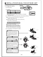
Page 24: ...y valve and 3 way s connect the service port into the projection of charge hose low for gaugemanifold Then connect the projection of charge hose center for gaugemanifold into vacuum pump To use vacuum pump 3 Vacuumize for over 15min And check the level gauge which should read 0 1 MPa 76 cm Hg at low pressure side After the completion of vacuumizing close the handle Lo in gaugemanifold and stop the...

Page 25: ...is cut off pull the power cable plug terminals of the low pressure pressure switch out 3 After confirming the power cable terminals of the low pressure pressure switch is cut off After powering on the unit again and switch to COOLING mode perform refrigerant gas recycling according to the normal refrigerant gas recycling procedure 4 After finishing refrigerant gas recycling cut off the power then ...

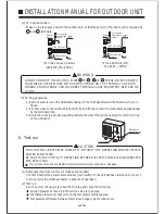
Page 26: ...odels Confirm whether the power source breaker main switch of the unit has been turned on for over 12 hrs to energize the crankcase heater in advance of operation 2 Test run Run the unit continuously for about 30 minutes and check the following Suction pressure at check joint of service valve for gas pipe Discharge pressure at check joint on the compressor discharge pipe Temperature difference bet...

Page 27: ...When strength is insufficient injury can result from a falling of the unit Execute the prescribed installation construction to prepare for earthquakes and the strong winds of typhoons and hurricanes etc Improper installations can result in accidents due to a violent falling over of the unit For electrical work please see that a licensed electrician executes the work while following the safety stan...

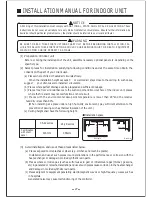
Page 28: ...Places free from air disturbances to the suction port and blowout hole of the indoor unit places where the fire alarm may not malfunction or short circuit d Places with the environmental dew point temperature is lower than 28 and the relative humidity is less than 80 When installing at a place under a high humidity environment pay sufficient attention to the prevention of dewing such as thermal in...

Page 29: ...nel dimensions 137 30 30 Ceiling panel wrap dimensions Ceiling panel wrap dimensions Hanging bolt position Ceiling hole size Panel dimensions 75 545 690 750 70 Pipe co nnection side b Hanger bolts installation Use care of the piping direction when the unit is installed Hanging bolt M10 Hole in anchor Hole in plug Insert Concrete Dimensions A Unit mm B C 1406 1600 1660 986 1180 1240 Model 36 42 ser...

Page 30: ... or making traps When connecting the drain pipe to unit pay suffcient attention not to apply excess force to the piping on the unit side Also fix the piping at a point as close as possible to the unit For drain pipe use hard PVC general purpose pipe VP 25 I D 1 which can be purchased locally When connecting insert a PVC pipe end securely into the drain socket before tightening securely using the a...

Page 31: ...gadget When doing this if the stretch for the needed height is higher than 500 mm the back flow quantity of drain at the event of interruption of the operation gets too much and it may cause overflow at the drain pan Therefore make the height of the drain pipe within the distance given in the sketch below Avoid positioning the drain piping outlet at a place where generation of odor may be stimulat...

Page 32: ... number of bends as much as possible Corner R should be as larger as possible Use a band etc to connect the main unit and the blowout duct flange Conduct the duct installation work before finishing the ceiling 8 Connection of suction exhaust ducts a Duct connection position i Fresh air inlet Inlet can be selected from the side or rear faces depending on the working conditions Use the rear fresh ai...

Reviews: