background image

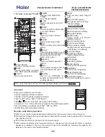
A

ON

OFF

TEMP

HEALTH

FAN

MODE

SLEEP

SWING

CLOCK

TIMER

SET

LOCK

LIGHT

RESET

STERILIZE

HEALTH AIRFLOW

FRESH

CODE

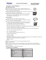
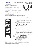
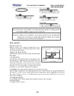
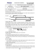
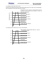
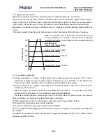
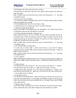
Raise 1 C

Drop for 2 C

Drop for 2 C

About 3 hours

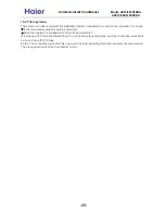
The Sleep running starts

The Sleep running stops

Set the

temperature

Close down

the machine

In heating

1 hour

1 hour

3 hours

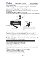
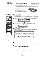
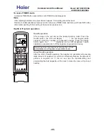
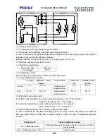
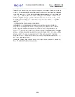
TIMER ON/OFF operation

Remote control unit

TIMER operation

Set Clock correctly before starting Timer operation (refer to page 2)

You can let unit start or stop automatically at following times: Before you wake

up in the morning, or get back from outside or after you fall asleep at night.

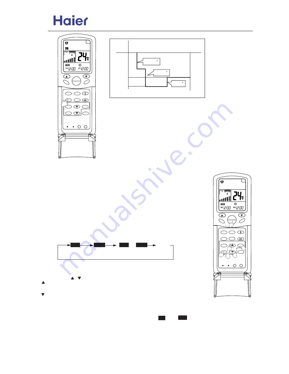
TIMER ON/OFF

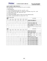
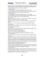
(1) After unit start, select your desired operation mode.

Operation mode will be displayed on LCD.

(2) TIMER mode selection

Press TIMER button to change TIMER mode.
Every time the button is pressed, display changes as follows:

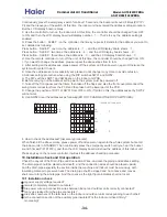
Remote

controller

Select your desired TIMER mide (TIMER ON or TIMEROFF) ON or OFF will flash.

(3) Timer setting

Press HOUR     /     button.

   Every time the button is pressed, time increases 1 min, If button is kept

pressed, time will change quickly.

   Every time the button is pressed, time decreases 1 min, If button is kept

pressed, time will change quickly. Time will be shown on LCD. It can be adjusted

within 24 hours.

(4) Confirming your setting

After setting correct time, press SET button to confirm, "        " or "         " stops flashing.

Time displayed: Unit starts or stops at x hour x min (TIMER ON or TIMER OFF)

Timer mode indicator on indoor unit lights up.

ON

ON

OFF

OFF

TIMER ON

TIMER OFF

TIMER ON-OFF

AM

12:00

PM

12:00

PM

12:00

AM

12:00

BLANK

ON

OFF

A

2

3

STERILIZE

HEALTH AIRFLOW

FRESH

CODE

4

5

6

ON

OFF

TEMP

HEALTH

FAN

MODE

SLEEP

SWING

CLOCK

TIMER

SET

LOCK

LIGHT

RESET

1

-43-

Commercial Air Conditioner


Model: AU18

/22

2XFERA 


AS072/092/122XVERA 

Summary of Contents for AS072XVERA

Page 1: ...tiple connection types with different types of indoor unit total indoor load can be up to 135 than the standard match Infrared control type Central control and full automation if connected with a central controller New friendly refrigerant R410a zero ODP environment protection Advanced technology DC inverter control function Health airflow and sterilize function for wall mounted unit more healthy ...

Page 2: ...y precaution 10 4 Net dimension of indoor and outdoor 12 5 Installation instructions 13 6 Parts and functions 36 7 Remote controller YR H65 37 8 Refrigerant diagram 45 9 Electrical control functions 47 10 Diagnostic information and trouble shooting 59 11 Electrical data 65 12 Performance curves 71 13 Noise level 75 14 Air velocity distribution 78 2 ...

Page 3: ...voltage 2 stands for 220 230V 50Hz 4 stands for 220V 60Hz N stand for 380 400V 50Hz Cooling Heating capacity 18 18000BTU h Product type B stands for cassette type C stands for convertible type D stands for duct S stands for wall mounted type E stands for ceiling concealed type U stands for outdoor unit Air Conditioner 1 2 Brief Introduction for T1 T2 T3 working condition 1 3 Operating Range of Air...

Page 4: ... Also the air blow direction can be set as step or stepless control much convenient to control Newly designed guarding plate of valve In order to protect the valve against the dust the rain or the snow etc we add a guarding plate to the valve Adopt the much friendlier refrigerant R410a The air conditioner system adopts the greatly friendly refrigerant R410a which is protective for the ozone layer ...

Page 5: ...re soon Central control function if connected with a detector and a central controller That is convenient for building management Weekly timing function if connected with a detector and a weekly timer Adjustable heating temperature compensation In heating mode the temperature compensation can be adjusted by the remote controller If you do not want the compensation you can set the compensation as 0...

Page 6: ... rating power input Max Running current Fan Item Model AU182XFERA Function Power source 1PH 220 230V 50Hz Rating capacity Maximum capacity Power input EER COP Fuse size recommended size TNB175FLBM1 MISTUBISHI ELEC Twin Rotary DC inverter 1 25 Outdoor unit Compressor Dimension L W H Heat exchanger Crankcase heater power Axial 1 670CC MEL 56 928 288 680 1015 405 760 850 700 500 35 about 3000 TP2M 7 ...

Page 7: ...U222XFERA AS092XVERA 2 AS122XVERA 2 Large drop and long piping installation will obviously reduce the total capacity Connecting method Flared Between I D O D 5 10 30 1 10 indoor unit lower than outdoor unit 15 indoor unit higher than outdoor 5 55 54 60 Piping Refrigerant R410A 2 0 30 20 Pipe 3 Φ6 35 3 Φ9 52 Defrosting method Automatic by reversible cycle Crankcase heater power 35 Dimension L W H 9...

Page 8: ... 7 6 10 6 PVC 11 4 16 4 Controller type Infrared YR H65 Refrigerant control PMV on outdoor unit Dimension L W H 795 197 265 880 315 330 Heat exchanger TP2M 7 0 35 Power source 1 220 230 50 Running current Fan Power cable 3 1 0 1 5mm 2 Communication cable 2x 0 75 1 25mm 2 must be shielded Function Capacity Capacity Dehumidifying capacity Flared Item Piping R410A R410A Pipe 6 35 6 35 9 52 9 52 Conne...

Page 9: ...Installation state the unit should be placed on the flat floor or be mounted in horizontal direction Testing method outdoor unit 1 air outlet from side the noise level is the average sound pressure level measured from front left right directions 2 air outlet from top the noise level is the average sound pressure level measured from front back left right directions measured point H height to the gr...

Page 10: ...r this manual should be as well transferred to the new user WARNING If any abnormal phenomena is found e g smell of firing please cut off the power supply immediately and contact the dealer to find out the handling method Don t dismantle the outlet of the outdoor unit The exposed fan is very dangerous which may harm human beings switch off In such case to continue using the conditioner will damage...

Page 11: ...e water leak electrical shock and fire hazard Call the dealer to take measures to prevent the refrigerant from leaking If conditioner is installed in a small room be sure to take every measure in order to prevent suffocation accident even in case of refrigerant leakage When conditioner is removed or reinstalled dealer should be responsible for them Incorrect installation may cause water leaking el...

Page 12: ...4 Net dimension of indoor and outdoor AU18 222XFERA 37 1 85463 870 305 225 Wall mounted unit 12 18 Commercial Air Conditioner Model AU18 222XFERA AS072 092 122XVERA ...

Page 13: ...ter check if the pressure in the pipe has reduced 1 Do not connect the power supply 1 Use piping material of the specified thickness 2 Do not use dirty pipe 3 Always flow nitrogen during welding work hand over trial running and adjustment maintenance panel installation gas leakage check additional refrigerant charging evacuation and drying leakage test refrigerant piping connection outdoor unit in...

Page 14: ...se Vacuum evacuation and refrigerant charging operation check Air tightness test Refrigerant additional charging Vacuum pump with adapter Vacuum drying Electronic scale Gas leakage detector Gas leakage test Refrigerant additional charging Work precautions Refrigerant check Before work check the used refrigerant and prepare materials matched to the refrigerant Refrigerant piping Observe the basics ...

Page 15: ... other things into the inlet outlet and swing louver Do not allow children to play with the air conditioner In no case should children be allowed to sit on the outdoor unit Specifications The refrigerating circuit is leak proof 1 Applicable ambient temperature range The machine is adaptive in following situation Model H05RN F 3G 4 0mm2 2 If the supply cord is damaged it must be replaced by the man...

Page 16: ...on storms and high winds Incorrect installation may cause the unit to fall down All electric work should be carried out by experienced personnel as per current regulations and this manual Incorrect installation or undersized electric cable may cause electric shock or fire risk All circuits must be earthed Ensure that no external forces will affect the terminal block and electric cable Poor wiring ...

Page 17: ... in a room entirely Place nearby a power receptacle with enough space around Refer to drawings Place where the distance of more than 1m from televisions radios wireless apparatuses and fluorescent lamps can be left In the case of fixing the remote controller on a wall place where the indoor unit can receive signals when the fluorescent lamps in the room are lightened Choose the installation place ...

Page 18: ...ropriate length and wrap it with tape making sure that no gap is left in the insulation pipe s cut line more than 10cm more than 10cm more than 60cm m ore than 25cm Arrangement of piping directions If there is the danger of the unit failing or overturning fix the unit with foundation bolts or with wire or other means If the location does not have good drainage place the unit on a level mounting ba...

Page 19: ... higher to avoid bad heating or cooling effect 2 Selecting a location for installation of the indoor units The maxinum allowable length of refrigerant piping and the maxmum allowable height difference between the outdoor and indoor units are listed below The shorter the refrigerant piping the better the performance Connect so that the piping is as short as possible Shortest allowable length per ro...

Page 20: ...p between every two indoor units Drop between the outdoor unit and the indoor unit 10 1 5 5 Size of the gas side connection pipe Pipe length when the compressor connects with two indoor units Pipe length when the compressor connects only one indoor unit Drop between the outdoor unit and the indoor unit 6 35 9 52 10 10 30 5 15 10 30 30 L1 L2 L3 m Total liquid piping length 30 45 Liquid pipe Gas pip...

Page 21: ...as Side 9 52mm 3 8 50N m 3 Attaching Drain Elbow Drain elbow Hose If the drain elbow is used please attach it as figure Flare nut Half union Torque wrench Spanner 5 On drainage Please install the drain hose so as to be downward slope without failure Please don t do the drainage as shown below Correct Incorrect Lean Damage of flare Crack Partial Too outside Pipe diameter Size A mm Liquid side Gas s...

Page 22: ...projection of charge hose low for gaugemanifold Then connect the projection of charge hose center for gaugemanifold into vacuum pump 2 Open the handle at low in gaugemanifold operate vacuum pump If the scale moves of gause low reach vacuum condition in a moment check 1 again 3 Vacuumize for over 15min And check the level gauge which should read 0 1MPa 76 cm Hg at low pressure side After the comple...

Page 23: ...minals its wiring method is as shown in the right figure remove the connecting screw put the screw through the ring on the end of the wire then connect to the terminal block and fasten screw Wiring method of straight terminals For the connection wire without orbicular terminals its wiring method is loosen the connection screw and insert the end of the connection wire completely into the Terminal b...

Page 24: ...onnection wire After connection the wire must be fastened by wire cover The wire cover shall press on the protection coat of the connection wire as shown in right top figure Note When connecting the wiring confirm the terminal number of indoor and outdoor units carefully Incorrect wiring will damage the controller of air conditioner or the unit can not operate Terminal block Wire cover A Wire cove...

Page 25: ...resses setting Make sure that all the stop valves are fully open Check the voltage supplied to the outdoor and indoor units please cinfirm that is 230V 6 After installation please fill in the following table for easy daily maintenance Indoor unit C Indoor unit B Indoor unit A 1PH 220 230V 50Hz Outdoor unit Power supply cable H05RN F 3G 4 0mm2 Communication cable Shield wire H05RN F 2X1 5mm2 Connec...

Page 26: ...start again for about 3 minutes 6 During cooling operation frost may ocur on the indoor unit or pipes this is normal 7 Operate the unit according to the operation manual Please kindly explain to our customers how to operate through the instruction manual Gas leakage from pipe connection Heat insulation treatment of pipe connection Are the connection wiring of indoor and outdoor unit firmly inserte...

Page 27: ...erforating the air conditioner s tubes with sharp or pointed items crushing or twisting any tubes or scraping the coatings off the surfaces If the refrigerant spurts out and gets into eyes it may result in serious eye injuries Do not obstruct or cover the ventilation grille of the air conditioner Do not put fingers or any other things into the inlet outlet and swing louver Do not allow children to...

Page 28: ...oner will damage the conditioner and may cause electrical shock or fire hazard When you need maintenance and repairment call dealer to handle it Incorrect mainten ance and repairment may cause water leak electrical shock and fire hazard Please let the dealer be responsible for installing the conditioner Incorrect installation may cause water leak elec trical shock and fire hazard Don t put fingers...

Page 29: ...r conditioner should be cleaned only after power supply is cut off to keep from shock or hurt Don t clean air conditioner with water Otherwise may cause shock Otherwise the poisonous chemicals may settle in air conditioner which harm the health of chemical allergic people When use the fumigating insecticide don t open air conditioner CAUTION Please ask the dealer or specialist to install never try...

Page 30: ...ing electric magnetic waves h Places with acid alkali vapuor TV radio acoustic appliances etc are at least 1 m far away to the indoor unit outdoor unit power supply wire connecting wire pipes otherwise images may be disturbed or noises be created As required take measures against heavy snow Air conditioner should be equipped with special power supply wire Chose the following locations a Capable of...

Page 31: ...ration is stopped When the remote controller is manipulated it gets the system back to the normal operation mode Disconnect power supply before clean the unit Don t touch it with wet hand Don t wash with hot water or solvent to clean the unit Air filter and outdoor cleaning 1 Open the inlet grill 2 Detach the Air filters 3 Use water or vacuum cleaner to clean it If it is extremely dirty wash it wi...

Page 32: ...on adhesive Tape Adhesive tape Connecting Hose Gypsum powder Drain hose Heat insulation material 5 Choose the installation place Install the indoor unit where the weight of the unit can be supported Install the indoor unit where the heat source and steam source are not close and the unit inlet and outlet are not blocked Install the indoor unit where the drainage is easy and the outdoor unit can be...

Page 33: ...ping direction to the mark of hole for left rear piping which is marked on heat insulation materials 1 Insert the drain hose into the dent of heat insulation materials of indoor unit 2 Insert the indoor outdoor electric cord from backside of indoorunit and pull it out on the front side then connect them 3 Coat the flaring seal face with refrigerant oil and connect pipes Cover the connection part w...

Page 34: ... has entered the address setting procedure But the LCD display board is blank F Use the controller to turn on the indoor unit At this time the controller should be changed from OFF to ON and then the LCD display board will display number 1 That is to say the address setting is enabled G Press the button SLEEP on the controller the times you press it stands for the address you want to set detailed ...

Page 35: ...for installation conform to requirements Winding up with Protective Plastic Tape The connection pipes drain pipe and the connection wires shall be wound up with PVC tape Notes The connection pipes shall also be wound up with insulating material to preserve the temperature The airing direction shall be from bottom to top 35 Commercial Air Conditioner Model AU18 222XFERA AS072 092 122XVERA ...

Page 36: ...8 37 06 4 3 4 06 4 3 4 18 4 3 4 3 4 18 4 6 6 84 5 6884 Commercial Air Conditioner Model AU18 222XFERA AS072 092 122XVERA 6 Parts and Functions Front panel Air inlet grille Air inlet grille Louver Display board 36 ...

Page 37: ...isplay 2 SWING 29 STERILIZE Fresh Air state display This function is optional HEALTH AIRFLOW FRESH STERILIZE CODE LOW MID HIGH AUTO 1 1 3 3 4 4 5 5 6 6 7 7 8 8 9 9 10 10 11 11 12 12 13 13 14 14 15 16 17 18 19 21 23 24 25 26 28 20 B A 27 22 Note This model does not have the following related display and function 18 21 30 HEALTHAIRFLOW Used to set healthairflow CODE A B selection For this unit pleas...

Page 38: ...unning The previous status appears on the display except TIMER SLEEP mode Press MODE button For each press operation mode changes as follows 4 Remote controller Press ON OFF button Unit stops running Press FAN For each press operation mode changes as follows Remote controller Unit runs at the speed displayed on LCD When fan speed is AUTO it is changed automatically according to the indoor temperat...

Page 39: ... controller Remote controller AUTO COOL DRY FAN HEAT LOW MID HIGH AUTO A ON OFF TEMP HEALTH FAN MODE SLEEP SWING CLOCK TIMER SET LOCK LIGHT RESET 1 2 3 STERILIZE HEALTH AIRFLOW FRESH CODE 5 3 4 A Dry operation Press ON OFF button Unit starts running The previous status appears on the display except TIMER SLEEP mode Press MODE button For each press operation mode changes as follows Select Drying op...

Page 40: ...ing and when entering this mode for the next time it will show the previous setting 4 1 2 3 Press FAN button For each press fan speed changes as follows Note In this mode temp can t be selected temp setting will not be shown in LCD display In Fan operation mode AUTO fan speed is not available Operation cycles are as follows LOW MID HIGH Unit runs at the speed displayed on LCD LOW MID HIGH ON OFF T...

Page 41: ...ws 4 3 Select temp button Press TEMP button Every time the button is pressed temp setting increases 1 C Every time the button is pressed temp setting decreases 1 C If the button is kept pressed setting will increase or decrease quickly Press ON OFF button 5 Unit stops running and when entering this mode for the next time it will show the previous setting In heat mode warm air will blow out after a...

Page 42: ...ised for 1 C after another hour It continues under that condition for 6 hours then the machine will be switched off The temperature is higher than the set temperature so as to avoid catching cold in sleeping 2 In heating the single cooling conditioners do not have the function After the Sleep running starts the temperature will drop for 2 C after another one hour The temperature will raise for 1 C...

Page 43: ... the button is pressed display changes as follows Remote controller Select your desired TIMER mide TIMER ON or TIMEROFF ON or OFF will flash 3 Timer setting Press HOUR button Every time the button is pressed time increases 1 min If button is kept pressed time will change quickly Every time the button is pressed time decreases 1 min If button is kept pressed time will change quickly Time will be sh...

Page 44: ...he unit begins health operation start the negative ion generation device Press the Health button again the displayed on the LCD disappears health operation is cancelled turn off the negative ion generation device Note When indoor fan motor does not work the unit will automatically turn off negative ion generation device Health operation After the start of Health operation the negative ion generato...

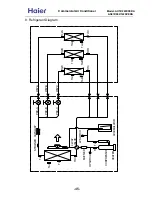
Page 45: ...mB TmC Tc2C Tc2B Tc2A Tc Te Tao Ts Td CAPILLARY ACCUMULATOR 4 WAY VALVE WAY C WAY B WAY A PMV C PMV B PMV A STRAINER MUFFLER HEATER COMPRESSOR LP SWITCH HP SWITCH Tc1 C Tc1 D Tc1C 45 Commercial Air Conditioner Model AU18 222XFERA AS072 092 122XVERA ...

Page 46: ...get SH cooling and SC heating control 11 LP switch 0 05 0 15Mpa Cut off the system when suction pressure is too low or system serious leakage to protect system 12 Accumulator 1 5L Separate the liquid refrigerant and gas refrigerant in suction line to avoid liquid flood back 13 Ts sensor 10K 25 To calculate the target SH and SC and control the start up of the compressor 14 Tc2 10K 25 To calculate t...

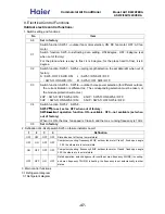
Page 47: ...5HP SW5 5 ON SW5 6 OFF 3HP SW5 5 ON SW5 6 ON 3 5HP SW5 5 OFF SW5 6 OFF C4 Switch function SW5 7 SW5 8 SW5 7 pre set set as OFF when out of factory SW5 8 silent operation function ON available OFF not available set when out of factory When it is ON the max fan speed is Class 6 and the max running frequency is 10Hz C8 Set in factory 2 Defination of 4 bit dip switch SW5 on failure indicator board 1 2...

Page 48: ...hermostat ON Thermostat OFF Adjustable lower limitation Cool dry 5 E 450 E standard open angle tolerance 5 E 80 E heat 60 E 450 E standard open angle tolerance 60 E 80 E 3 3 4 Standard open angle control In Cool Dry mode standard open angle outdoor ambient temp 20 250 pulse E Outdoor ambient temp 20 210 pulse E In Heat mode standard open angle outdoor ambient temp 10 pulse E outdoor ambient temp 1...

Page 49: ...e electric heater will be electrified When TA 32degree or compressor running the electric heater will be off Heater ON OFF Ambient temp TA 27 32 3 6 Control of liquid spray valve SV2 According to the compressor discharging temp open or close the SV2 Control condition A In every mode including defrosting and oil return operation the control can work B In 3 minutes after compressor startup ignore th...

Page 50: ...e the condition of outdoor heat exchanger if the temp is over 7 for 60 seconds in all or is up to 12 for 30 seconds in all the defrosting will be over 3 7 3 Compulsory defrosting control Enter condition in heating mode after receiving the compulsory defrosting signal from indoor unit the unit will perform the compulsory defrosting operation Cancel condition Te 12 and keep for 1 minute or the defro...

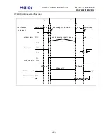
Page 51: ...artup compressor 0HZ 0HZ 5s outdoor motor ON send defrosting signal to indoor Auto OFF 4 way valve ON OFF 15s ON Spray valve SV2 OFF 450 pulse 450 pulse 350 pulse E all EEVs auto open angle auto open angle all indoor motors ON OFF anti cold air function 51 Commercial Air Conditioner Model AU18 222XFERA AS072 092 122XVERA ...

Page 52: ...imes in 1 hour the unit will stop and alarm Reduce FQY rapidly 2HZ S Reduce FQY rapidly 1HZ S Reduce FQY slowly 1HZ 10S Remain FQY Increase FQY slowly 1HZ 10S Discharging temp TD If keeping for 10s the unit stops 3 minutes later the unit can re startup If in 60 minutesthe unit occurs alarm for 3 times the failure can be eliminated Reduce FQY rapidly 2HZ S Reduce FQY rapidly 1HZ S Reduce FQY slowly...

Page 53: ...ntinously alarm will occur When unit stops the reason that system still checks the low pressure in a long time stop make protection for the compressor on the condition of great refrigerant leakage The reason that low pressure switch action time is 30 seconds when compressor stops low pressure does not change so it will be shorter than the set time in operation 3 When compressor starts up in 8 minu...

Page 54: ...for 5 seconds unit stops and alarm occurs 3 minutes later restart up If it occurs 3 times in 1 hour it will always alarm and stop electrify again and failure will be cleared Te 30 35 40 45 50 Normal operation Min running FQY 20HZ SV2 OFF 20HZ SV2 ON 20HZ Keep for 5 seconds unit stops and alarm occurs 3 minutes later restart up If it occurs 3 times in 1 hour it will always alarm and stop electrify ...

Page 55: ...l address 2 1 1 1 1 1 1 0 Central control address 127 1 1 1 1 1 1 1 Central control address 128 0 Indoor communication address set by remote controller 1 Indoor communication address set by dip switch SW02 1 2 3 4 5 6 7 8 description 0 0 AS072 capacity selection 0 1 AS092 capacity selection 1 0 AS122 capacity selection 0 0 LCD display board LCD remote receiver 1 1 LED display board LED remote rece...

Page 56: ...ding to the room temp and the set temp When room temp set temp entering cooling mode When room temp set temp entering heating mode Mode conversion will be confirmed after compressor has stopped for 15 minutes 7 Abnormal operation When outdoor modes from the request of indoor unit conflict the one entering firstly will take priority After indoor receives the ON command from remote controller it wil...

Page 57: ...is valid only in heating mode if indoor mid coil temp is over about 65 degree continuously for 10 seconds indoor will stop while when indoor mid coil temp is below 52 degree indoor will resume Note The above temp point has taken fuzzy control and has tolerance 1 according to the different state 14 Timer operation TIMER ON TIMER OFF TIMER ON OFF Timer will count according to the time difference bet...

Page 58: ... the temperature compensation in heating mode with the remote controller No compensation in cooling mode In 24 heating mode press SLEEP button 8 times continuously indoor buzzer sounds 5 times that shows temp compensation works Switch on the unit in heating mode by the remote controller press TEMP button to set the set temp so temperature compensation the current set temp 24 For example if the set...

Page 59: ... Faulty temperature sensor Tm 4 Sensor disconnected or broken or at wrong position or short circuit Faulty EEPROM on indoor 5 Faulty indoor unit PCB Abnormal communication between indoor and outdoor unit 6 Wrong connection or the wires be disconnected or wrong address setting of indoor units or faulty PCB or faulty power supply Indoor unit address repeated 9 Wrong setting of indoor unit address Ce...

Page 60: ...frigerant shortage 10 IPM protection IPM over current or short circuit or IPM temperature too high or IPM input voltage too low or faulty SPDU EEPROM fault Faulty outdoor unit PCB Over hot protection of compressor Serious lack of refrigerant of the system or the ambient temperature too high or PMVs be blocked DC fan motor fault Fan is blocked or the terminal is disconnected from the PCB Faulty 4 w...

Page 61: ...de on indoor PCB flash in turn replace display panel and check again yes no no check if display panel and the unit matched well Trouble 1 No display on the operation panel no start PCB is faulty and repalce it check again replace sensor and check again replace sensor and check again check if sensor resistor value is correct no no yes yes yes check if sensor is in open circuit or PCB port is not in...

Page 62: ... the fan motor input connection is fixed badly CN3 on PCB Trouble 6 Indoor fan motor failure AC fan motor has not 50Hz zero crossing detection Trouble 5 Indoor repeated unit number Trouble 4 Indoor PCB EEPROM data is wrong 1 If the failure occurs when being electrified for the first time that shows EEPROM 8 bit pin not fixed firmly or damaged 2 If the failure occurs when running that shows EEPROM ...

Page 63: ...ged please replace the power module then re wiring as per the wiring diagram 70 possibility 2 Short circuit in power board results in the power module damaged 15 possibility 3 Damaged compressor results in this failure 10 possibility 4 Main control board is faulty replace it 5 possibility replace outdoor motor and check again check if the outdoor motor has power input replace pressure switch conne...

Page 64: ...startup normally in heating mode except for defrost check if the 2 straight lugs on the pressure switch work badly no no no check if the connector between pressure switch and PCB is fixed badly or damaged CN20 on PCB no Failure 11 Low pressure switch failure Reason 1 Too low system pressure causes that the unit stops and the compressor protection works the failure can be resumed 2 Pressure switch ...

Page 65: ...tor capacitor capacitor BL BLUE BL OR B W Y G Y G B W SPDU P N RO ACL RI ACN W V U RL1 POWER BOARD CIRCUIT CN7 CN8 220VAC L CN3 CN4 BOARD CIRCUIT CONTROL CN5 L N CN1 TO SPDU 4WV DEBUG_LED LED CN7 CN2 CN1 CN13 CN14 CN5 CN3 H CN23 CN20 HP LP CN19 Y G YELLOW GREEN W WHITE OR ORANGE R RED B BLACK stop down start up SW1 SW2 SW4 SW3 1 2 34 ON N CN8 L BUS PTC 8 7 6 5 4 3 2 1 ON CN6 SV2 PMV_A PMV_D PMV_C ...

Page 66: ...11 2 Circuit diagram Outdoor circuit diagram 66 Commercial Air Conditioner Model AU18 222XFERA AS072 092 122XVERA ...

Page 67: ...Indoor circuit diagram 67 Commercial Air Conditioner Model AU18 222XFERA AS072 092 122XVERA ...

Page 68: ...059 1 R25 10KΩ 3 B25 50 3700K 3 2 R25 23KΩ 2 5 B25 50 4200K 4 liquid pipe temp sensor 001A3800103 001A3900004 R25 10KΩ 3 B25 50 3700K 3 discharging temp sensor R80 50KΩ 3 B25 80 4450K 3 mid condensor temperature sensor R25 10KΩ 3 B25 50 3700K 3 outdoor ambient temp sensor R25 10KΩ 3 B25 50 3700K 3 AS072XVERA AS092XVERA AS122XVERA AU182XFERA 68 AU222XFERA Commercial Air Conditioner Model AU18 222XF...

Page 69: ...1 7 2793 47 186 3 3 26 4 57 3 11 6 2636 48 178 4 4 25 61 58 2 9 5 2489 49 170 9 5 24 41 59 2 81 4 2351 50 163 7 6 23 27 60 2 72 3 2221 51 155 9 7 22 2 61 2 63 2 2099 52 150 4 8 21 18 62 2 54 1 1984 53 144 2 9 20 21 63 2 49 0 1877 54 138 3 10 19 3 64 2 38 1 1775 55 132 7 11 18 43 65 2 3 2 1680 56 127 3 12 17 61 66 2 23 3 1590 57 122 1 13 16 83 67 2 16 4 1506 58 117 2 14 16 09 68 2 09 5 1426 59 112 ...

Page 70: ... 93 38 12 77 3 99 04 39 12 23 2 93 52 40 11 71 1 88 35 41 11 22 0 83 5 42 10 76 1 78 94 43 10 31 2 74 67 44 9 89 3 70 65 45 9 49 4 66 88 46 9 1 5 63 33 47 8 74 6 60 48 8 39 7 56 86 49 8 05 8 53 91 50 7 73 9 51 13 51 7 43 10 48 51 52 7 14 11 46 04 53 6 86 12 43 72 54 6 6 13 41 52 55 6 34 14 39 45 56 6 1 15 37 5 57 5 87 16 35 66 58 5 65 17 33 92 59 5 44 18 32 27 60 5 24 19 30 72 20 29 25 21 27 86 R2...

Page 71: ...0000 16 10 18 12 20 14 5 21 15 22 16 24 17 26 18 indoor WB DB Heating capacity W 6 7 4 5 1 2 1 0 6 5 7 6 12 10 16 15 Power input curves in heating mode 1700 1900 2100 2300 2500 2700 2900 16 10 18 12 20 14 5 21 15 22 16 24 17 26 18 indoor WB DB Power input W 6 7 4 5 1 2 1 0 6 5 7 6 12 10 16 15 71 Commercial Air Conditioner Model AU18 222XFERA AS072 092 122XVERA ...

Page 72: ...7 19 30 22 32 24 indoor DB WB Cooling capacity W 5 20 25 32 35 40 Power input curves in cooling mode 0 500 1000 1500 2000 2500 3000 18 12 20 14 22 16 25 18 27 19 30 22 32 24 indoor DB WB Power input W 5 20 25 32 35 40 72 Commercial Air Conditioner Model AU18 222XFERA AS072 092 122XVERA ...

Page 73: ... B 09 09 12 mainly cooling 1 56 1 56 2 18 1 50 5 30 5 80 0 50 1 65 2 30 2 29 7 40 10 20 3 21 A 07 14 cooling and heating 2 0 4 1 1 00 6 10 6 50 0 47 2 20 2 90 2 20 9 76 12 90 2 77 D 09 12 cooling and heating 2 5 3 2 1 00 5 70 6 20 0 47 2 00 2 90 2 20 8 87 12 90 2 85 C 09 14 cooling and heating 2 4 4 0 1 00 6 40 6 50 0 47 2 20 2 90 2 20 9 76 12 90 2 91 C 12 12 cooling and heating 3 2 3 2 1 00 6 40 ...

Page 74: ... 09 09 12 mainly cooling 2 05 2 05 2 55 1 50 6 65 7 00 0 55 1 80 2 30 2 50 7 99 10 20 3 69 A 07 14 cooling and heating 2 30 4 60 1 20 6 90 7 20 0 55 2 20 2 90 2 50 9 76 12 90 3 14 C 09 12 cooling and heating 2 90 3 80 1 20 6 70 7 20 0 55 2 20 2 90 2 50 9 76 12 90 3 05 C 09 14 cooling and heating 2 75 4 45 1 20 7 20 7 20 0 55 2 20 2 90 2 50 9 76 12 90 3 27 C 12 12 cooling and heating 3 60 3 60 1 20...

Page 75: ...ed cooling low fan high fan med fan low heating high heating med heating low 1 3 octave band noise level AS072XVERA 0 0 5 0 10 0 15 0 20 0 25 0 30 0 35 0 40 0 45 0 50 0 55 0 60 0 65 0 2 5 0 3 1 5 4 0 0 5 0 0 6 3 0 8 0 0 1 0 0 0 1 2 5 0 1 6 0 0 2 0 0 0 2 5 0 0 3 1 5 0 4 0 0 0 5 0 0 0 6 3 0 0 8 0 0 0 1 0 0 0 0 1 2 5 0 0 1 6 0 0 0 2 0 0 0 0 2 5 0 0 0 3 1 5 0 0 4 0 0 0 0 5 0 0 0 0 6 3 0 0 0 8 0 0 0 0 ...

Page 76: ...ng low fan high fan med fan low heating high heating med heating low 1 3 octave band noise level AS092XVERA 0 0 5 0 10 0 15 0 20 0 25 0 30 0 35 0 40 0 45 0 50 0 55 0 60 0 65 0 2 5 0 3 1 5 4 0 0 5 0 0 6 3 0 8 0 0 1 0 0 0 1 2 5 0 1 6 0 0 2 0 0 0 2 5 0 0 3 1 5 0 4 0 0 0 5 0 0 0 6 3 0 0 8 0 0 0 1 0 0 0 0 1 2 5 0 0 1 6 0 0 0 2 0 0 0 0 2 5 0 0 0 3 1 5 0 0 4 0 0 0 0 5 0 0 0 0 6 3 0 0 0 8 0 0 0 0 1 0 0 0 ...

Page 77: ...ng low fan high fan med fan low heating high heating med heating low 1 3 octave band noise level AS122XVERA 0 0 5 0 10 0 15 0 20 0 25 0 30 0 35 0 40 0 45 0 50 0 55 0 2 5 0 3 1 5 4 0 0 5 0 0 6 3 0 8 0 0 1 0 0 0 1 2 5 0 1 6 0 0 2 0 0 0 2 5 0 0 3 1 5 0 4 0 0 0 5 0 0 0 6 3 0 0 8 0 0 0 1 0 0 0 0 1 2 5 0 0 1 6 0 0 0 2 0 0 0 0 2 5 0 0 0 3 1 5 0 0 4 0 0 0 0 5 0 0 0 0 6 3 0 0 0 8 0 0 0 0 1 0 0 0 0 0 1 2 5 ...

Page 78: ...dition Fan speed high Operation mode fan Voltage 230V 50Hz Fig 2 top view flow control panel horizontal lourer right and left 10 9 8 7 6 5 4 3 2 1 1 1 2 2 0 m 0 25 0 5 1 0 2 0 m 10 9 8 7 6 5 4 3 2 1 0 3 1 8 1 0 25 unitm s m 0 1 2 3 4 5 6 0 5 m 1 0 2 0 3 0 1 8 3 m 10 9 8 7 6 5 4 3 2 1 0 m 3 2 0 1 2 1 2 0 1 0 0 5 0 25 1 0 0 5 0 25 unit m s unit m s unit m s m 78 Commercial Air Conditioner Model AU18...

Page 79: ...Commercial Air Conditioner Model AU182XFERA AS072 092 122XVERA Sincere Forever Haier Group Haier Industrial Park No 1 Haier Road 266101 Qingdao China http www haier com ...

Reviews: