background image

ATW Service Manual

SYJS-03-2019REV.A

Edition: 2019-03

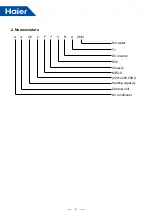
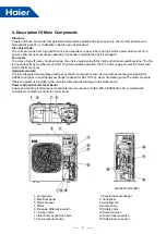
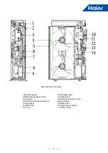
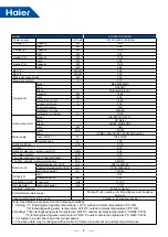
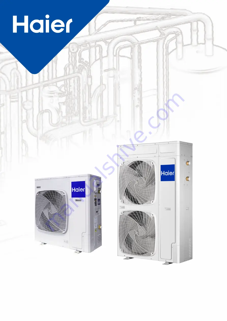
Summary of Contents for AU082FYCRA(HW)

Page 1: ...ATW Service Manual SYJS 03 2019REV A Edition 2019 03 ...

Page 2: ...9 Electric Characteristics 16 10 Capacity Tables 17 11 Operation Limits Delivery Leaving 23 12 Water Pressure Drop 25 13 Sound Level 27 14 Installation 28 15 PCB Photo 55 16 Dip Switch Setting 56 17 Digital Tube Display 57 18 Startup Running Maintenance 59 19 YR E27 Optional wired controller 62 20 Error Code 73 21 Troubleshooting 74 22 APPENDIX Sensor Resistance Table 101 ...

Page 3: ...082FYCRA HW 220 240 1 50 60 8kW DC Inverter Coaxial Heat pump Built in R32 Model Power Supply V Ph Hz Capacity Compressor type Heat exchanger A C mode Hydraulic module Refrigerant AU112FYCRA HW 220 240 1 50 60 11kW DC Inverter Tubes in shell Heat pump Built in R32 AU162FYCRA HW 220 240 1 50 60 16kW DC Inverter Heat pump Built in R32 ...

Page 4: ...2 2 Nomenclature A U 08 2 F Y C R A HW Hot water T1 DC inverter R32 Chassis MRV S 220 240V 50Hz Heating capacity Outdoor unit Air conditioner ...

Page 5: ... heating from 20 C to 35 C By adopting high efficiency Coaxial heat exchanger or tubes in shell heater exchanger the energy consumption can be reduced Compact devices with advanced function and friendly user interface The Heat pump can be controlled by optional wired controller YR E27 Fully integrated and built in hydraulic module such as Coaxial heat exchanger or tubes in shell heater exchanger w...

Page 6: ...or with built in thermal cut out Hydraulic module It is fully integrated and equipped with key hydraulic components such as Coaxial heat exchanger applied for AU082 and tubes in shell heater exchanger applied for AU112 162 water circulating pump The water pressure difference switch is provided in the units to protect against damage to the water pump Power and control electrical panel Power and con...

Page 7: ...Differential pressure switch 4 Axial flow fan 5 Condenser 6 Electronic expansion valve 7 Shell and tube heat exchanger 8 Accumulator 9 Compressor 10 Safety valve 11 Buffer tank 12 High pressure switch 13 Pump 14 4 Ways valve AU112 162 FYCRA HW ...

Page 8: ...ressure drop of heat exchanger kPa 45 The Max and Min water inlet pressure kPa 500 150 Outdoor unit Net dimension W H D mm 950 965 395 Packing dimension W H D mm 1010 990 458 Net Gross weight kg 87 90 Refrigerant Type R32 Charged volume kg 1 15 Connection wiring Power wire mm2 3 10 0 Pipe diameter Water inlet outlet inch 1 1 4 Controller optional Wired controller Ambient temperature range Cooling ...

Page 9: ...pressure drop of heat exchanger kPa 40 The Max and Min water inlet pressure kPa 500 150 Outdoor unit Net dimension W H D mm 950 1490 380 Packing dimension W H D mm 1010 1520 458 Net Gross weight kg 139 142 Refrigerant Type R32 Charged volume kg 2 40 Connection wiring Power wire mm2 3 10 0 Pipe diameter Water inlet outlet inch 1 1 4 Controller optional Wired controller Ambient temperature range Coo...

Page 10: ... pressure drop of heat exchanger kPa 40 The Max and Min water inlet pressure kPa 500 150 Outdoor unit Net dimension W H D mm 950 1490 380 Packing dimension W H D mm 1010 1520 458 Net Gross weight kg 139 142 Refrigerant Type R32 Charged volume kg 2 60 Connection wiring Power wire mm2 3 10 0 Pipe diameter Water inlet outlet inch 1 1 4 Controller optional Wired controller Ambient temperature range Co...

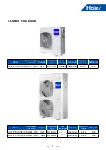
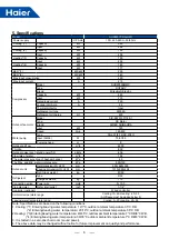
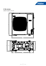
Page 11: ...9 405 410 600 174 174 450 950 965 395 6 Dimensions AU082FYCRA HW Unit mm ...

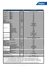
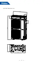
Page 12: ...10 AU112 162FYCRA HW Unit mm 1490 950 380 187 405 410 600 174 174 450 170 ...

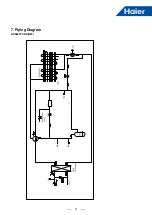
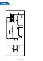
Page 13: ...11 AU082FYCRA HW 7 Piping Diagram ...

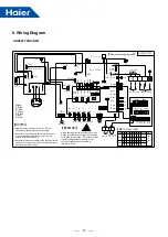
Page 14: ...12 AU112 162FYCRA HW ...

Page 15: ...U112 162FYCRA HW ACCU Used to separate the gas and liquid 90 350 Refrigerant valve ALL Used to charge the refrigerant to unit 7 Service valve AU112 162FYCRA HW Used to detect the pressure HPb59 1 S12 5 Flow switch AU082FYCRA HW DPS Detect Flow rate 0 012MPa OFF 0 009MPa ON AU112 162FYCRA HW 0 008MPa OFF 0 0055MPa ON Pump AU082FYCRA HW Pump Transport liquid Pumping head 8m AU112 162FYCRA HW Pumping...

Page 16: ... W B W B W W CN41 BL CN18 R COM R CN11 THO TW I TH I TWO W CN45 BL CN59 W CN43 Y CN44 W CN47 BL CN53 Y CN58 BL CN57 B CN56 R CN40 N L Wire controller Docking connector Water board LEVA1 M R CN8 SV1 SV2 1 0 0 MODE BM2 N O 1 2 3 4 5 6 7 8 0 0 0 BM2 0 1 82 100 0 1 0 0 0 0 0 0 0 0 0 1 0 0 Remarks W CN1 SMG1 SMG2 SW4 SW5 SW6 SW7 UP DOWN EXIT ENTER W CN2_1 W CN2 Display board L N W CN24 P OUT I O A Q Ce...

Page 17: ...closed for more than 10 minutes to ensure that the voltage between P and N on the converter board has been reduced to less than DC 20V Water board Display board Wire controller Docking connector Pd Ps OUT I O Centralized controller 0 means OFF 1 means ON ACL ACN HEATER SV1 SV2 4WV DCFAN1 DCFAN2 LED1 4 Symbol Signification Live Wire Neutral Wire Heater unloading valve spray valve 4 way valve up fan...

Page 18: ...W 50Hz 220 240V 1Ph 198V 264V 21 3 32 4 2 0 18 0 8 AU112FYCRA HW 50Hz 220 240V 1Ph 198V 264V 24 3 32 8 5 0 18 0 18 0 8 0 8 AU162FYCRA HW 50Hz 220 240V 1Ph 198V 264V 31 7 40 14 0 18 0 18 0 8 0 8 Remark MCA Min Current Amps A MFA Max Fuse Amps A MSC Max Starting Amps A OFM Outdoor Fan Motor FLA Full Load Amps A kW Rated Motor Output kW ...

Page 19: ... 45 5 92 1 66 6 46 2 21 3 09 2 15 35 6 73 1 89 7 34 2 95 4 19 2 92 25 7 66 2 15 8 35 4 30 6 03 4 12 15 8 48 2 37 9 24 6 28 8 39 6 01 10 8 71 2 44 9 50 8 49 10 20 8 08 DB Water flow temperature 10 45 5 16 1 44 5 67 1 97 2 69 1 91 35 6 06 1 70 6 67 2 63 3 64 2 60 25 6 67 1 87 7 34 3 82 5 25 3 66 15 7 34 2 05 8 07 5 59 7 30 5 35 10 7 71 2 16 8 48 7 55 8 88 7 19 DB Water flow temperature 7 45 4 24 1 2...

Page 20: ...7 3 56 13 05 2 83 3 49 2 51 35 13 22 4 63 14 54 3 81 5 07 3 29 25 14 43 5 05 15 88 5 06 7 62 4 47 15 15 21 5 32 16 73 7 06 8 52 5 67 10 15 97 5 59 17 57 9 08 9 78 8 80 DB Water flow temperature 10 45 10 24 3 17 11 77 2 49 3 07 2 21 35 12 91 4 00 14 85 3 35 4 46 2 90 25 13 96 4 33 16 05 4 46 6 70 3 94 15 15 31 4 75 17 61 6 21 7 50 4 99 10 15 91 4 93 18 29 7 99 8 61 7 75 DB Water flow temperature 7 ...

Page 21: ... 61 13 25 2 74 3 65 2 74 35 15 30 4 59 16 06 3 62 5 26 3 44 25 15 53 4 66 18 63 5 01 7 81 4 45 15 17 05 5 12 20 46 6 81 11 47 5 68 10 17 53 5 26 21 03 10 50 11 20 9 63 DB Water flow temperature 10 45 11 44 3 43 12 59 2 33 2 85 2 31 35 14 84 4 45 16 32 3 00 4 02 2 89 25 14 13 4 24 15 54 4 04 5 75 3 77 15 15 52 4 66 17 07 5 41 8 78 4 88 10 15 95 4 79 17 55 9 78 10 58 9 47 DB Water flow temperature 7...

Page 22: ...0 1 5 21 1 25 5 68 3 18 3 50 2 67 3 4 4 80 1 15 5 28 3 03 3 31 2 50 7 8 4 14 1 03 4 55 2 84 3 06 2 21 15 16 3 52 0 88 3 87 2 67 2 88 2 10 20 21 1 94 0 48 2 13 2 66 2 73 1 97 DB WB Water flow temperature 45 35 24 11 53 3 58 12 87 5 98 6 58 5 86 27 19 10 98 2 74 12 14 5 31 5 78 5 03 20 19 10 61 2 50 11 46 4 73 5 09 4 35 10 9 8 35 1 98 9 02 3 75 3 98 3 45 7 6 7 50 1 80 8 65 3 20 3 64 3 18 2 1 5 36 1 ...

Page 23: ...55 8 91 3 24 3 29 2 91 3 4 7 82 2 35 8 21 3 08 3 13 2 77 7 8 6 93 2 08 7 28 2 72 2 76 2 45 15 16 6 43 1 93 6 75 2 46 2 49 2 21 20 21 3 22 0 96 3 38 2 25 2 27 2 04 DB WB Water flow temperature 45 35 24 16 8 5 04 18 48 5 39 5 42 4 55 27 19 15 68 4 70 17 25 4 56 4 83 3 87 20 19 14 42 4 33 15 86 4 37 4 44 2 78 10 9 12 19 3 66 14 62 3 69 3 75 3 20 7 6 10 50 3 15 13 65 3 20 3 54 3 06 2 1 7 21 2 16 7 93 ...

Page 24: ...2 14 10 14 2 78 3 18 2 51 3 4 9 08 2 09 9 90 2 76 3 04 2 50 7 8 8 56 1 97 9 33 2 61 2 71 2 23 15 16 7 94 1 98 8 65 2 46 2 55 2 28 20 21 4 76 1 19 5 19 1 79 1 94 1 66 DB WB Water flow temperature 45 35 24 21 83 5 02 23 79 4 58 5 63 4 93 27 19 20 94 4 82 22 82 4 32 5 31 4 65 20 19 19 87 4 37 21 85 4 08 5 01 4 39 10 9 16 70 3 67 18 36 3 44 3 83 3 41 7 6 15 00 3 30 16 46 3 25 3 47 3 13 2 1 9 77 2 15 1...

Page 25: ...t Multiply the performance figures by the values given in the following table cPf correction factor of heating cooling capacity cQ correction factor of flow rate cdp correction factor of pressure drop Freezing point C 0 5 10 15 20 25 Percentage of ethylene glycol in weight 0 12 20 28 35 40 cPf 1 0 98 0 97 0 965 0 96 0 955 cQ 1 1 02 1 04 1 075 1 11 1 14 cdp 1 1 07 1 11 1 18 1 22 1 24 ...

Page 26: ...Refers to upper parameters for the charged volume b Fouling Factors The performance data given refer to conditions with clean evaporator plates fouling factor 1 For different fouling factors multiply the figures in the performance tables by the coefficient given in the following table Fouling factors Evaporator m 2 C W f1 fk1 fx1 4 4 10 5 0 86 10 4 0 96 0 99 0 99 1 72 10 4 0 93 0 98 0 98 f1 correc...

Page 27: ...25 12 Water Pressure Drop ...

Page 28: ...26 ...

Page 29: ...tdoor unit 14 9 2a X Y 13 d d d d d 2b 0 5c c 1 17 4 2 16 8 3 12 11 7 6 10 15 5 Z Model Noise level dB AU082FCYRA HW 61 AU112FCYRA HW 63 AU162FCYRA HW 68 Note It is tested 1 meter d away from the machine in a semi anechoic room sound power ...

Page 30: ...l in with indelible ink 1 the factory refrigerant charge of the product 2 the additional refrigerant amount charged in the field and 1 2 the total refrigerant charge on the refrigerant charge label supplied with the product The filled out label must be adhered in the proximity of the product charging port e g onto the inside of the stop value cover A contains fluorinated greenhouse gases covered b...

Page 31: ...ean other than those recommended by the manufacturer The appliance must be stored in a room without continuously operating ignition sources the radius of the storage area should be no less than 2 5 m for example open flames an operating gas appliance or an operating electric heater Do not pierce or burn Be aware that refrigerants may not contain an odour The appliance must be installed operated an...

Page 32: ...nal overheating electrical shock fire or explosion If any refrigerant has leaked out during the installation work ventilate the room The refrigerant produces a toxic gas if exposed to flames may cause explosion After all installation is complete check to make sure that no refrigerant is leaking out The refrigerant produces a toxic gas if exposed to flames may cause explosion When installing or rel...

Page 33: ... validity shall be equipped inside the driver s cab 8 Orange white or red white reflective stripes shall be pasted on the sides and tail of the transporting vehicles to remind the vehicles behind of keeping distance 9 The transporting vehicles shall run at a constant speed and heavy acceleration deceleration shall be avoided 10 Combustibles or the static articles cannot be transported simultaneous...

Page 34: ...le ventilation shall be maintained at the place of installation doors and windows are opened 2 Open fire or high temperature heat source including welding smoking and oven higher than 548 is not allowed within the scope of flammable refrigerant 3 Anti static measures shall be taken such as the wearing of cotton clothes and cotton gloves 4 The place of installation shall be convenient for installat...

Page 35: ...f with a cutting knife Connection is only allowed after re flaring the same to the outdoor unit Qualification Requirements of Maintenance Personnel 1 All the operators or the maintenance personnel involved in refrigerating circuits shall be provided with the effective certificate issued by an industry accepted assessment institute to ensure that they are qualified for safety disposal of refrigeran...

Page 36: ...linders acetylene cylinders and oxygen cylinders shall be placed separately The distance between the gas cylinders above and the working area involved in open fire shall be at least 6m The anti backfire valve shall be installed for the acetylene cylinders The color of the acetylene cylinders and oxygen cylinders installed shall meet the international requirements The warning sign of No Fire No Smo...

Page 37: ...refrigerant inside The cylinders of refrigerant shall be kept upright and be fixed After maintenance of the refrigeration system the system shall be sealed with a safe manner The maintenance in progress shall not damage or lower the original class of safety protection of the system Maintenance of Electrical Components Partial of the electrical component under maintenance shall be subject to inspec...

Page 38: ... that no refrigerant is inside the outdoor unit and the system refrigerant has been discharged and cleared The refrigeration pipelines cannot be cut with a welding gun under any circumstance The refrigeration pipelines must be disassembled with a pipe cutter and the disassembly must be carried out around a ventilation opening Refrigerant Charging Procedures The following requirements are added as ...

Page 39: ...city of which shall match with the refrigerant amount charged in the whole refrigeration system All cylinders to be used are designated for the recovered refrigerant and labeled for that refrigerant Dedicated Cylinder for Refrigerant Recovery The cylinders shall be equipped with pressure relief valves and stop valves under favorable state The empty cylinder shall be vacuumized before usage and be ...

Page 40: ...e base should be checked for any damages If the damaged base is not repaired the unit may fall down and cause accidents Air conditioner can t be installed in the environment with inflammable gases because the inflammable gases near air conditioner may cause fire and explosion hazard Please let the dealer be responsible for installing the conditioner Incorrect installation may cause water leak elec...

Page 41: ...unit and present a risk of electric shock smoke fire or explosion Do not touch the fins on the heat exchanger with bare hands for they are sharp and dangerous Only use refrigerant R32 as indicated on the unit when installing or relocating the unit The use of any other refrigerant or an introduction of air into the unit circuit may cause the unit to run an abnormal cycle and abnormal cycle and caus...

Page 42: ... ether oil or alkylbenzene to coat flares and flange connections A large amount of mineral oil will cause the refrigerating machine oil to deteriorate Exercise special care when handling the tools An introduction of foreign objects such as dust dirt or water into the refrigerant cycle will cause the refrigerating machine oil to deteriorate Use liquid refrigerant to charge the system Charge the uni...

Page 43: ...t breaker remote switch switch Type B fuse molded case circuit breaker with a proper current capacity The use of large capacity fuses steel wire or copper wire may damage the unit or cause smoke or fire Properly dispose of the packing materials Things such as nails may be included in the package Dispose of them properly to prevent injury Plastic bags present a choking hazard to children Tear up th...

Page 44: ...set point with central heating is 55 C which enables use of radiator systems as well as fan coil or radiant systems The entire range complies with the requirements of ErP Directive 2009 125 EC and ELD 2010 30 EC Various hydraulic electric and electronic kits are available which enable flexible use in all circumstances 8kW 11kW and 16kW mono phase inverter air water heat pumps for winter and summer...

Page 45: ...grees 0 7 1 0 meters Do not remove packing tape and packing box As shown in the picture rope through the wood base around the lifting hole rope 0 7 1 0 met ers Manual handling CAUTION In the installation and commissioning the outdoor machine do not put any irrelevant material to ensure that there is no debris inside the machine or there may be a fire or accident Pay attention to the following poin...

Page 46: ...place blowing salty air seaside etc Exsits the strong coal smoke The place with high humidity The place where there is device emitting Hertzian waves The place where voltage changes greatly Note 1 In snowy area install the unit under the bracket or the snow proof cover against the accumulative snow on the unit 2 Do not install the unit at the place where the flammable gas will leak 3 Install the u...

Page 47: ...f the front and back shall be lower than the outdoor unit The installation service spaces shown in the illustrations are based on an air intake temperature of 95 F 35 C DB for COOL operation In regions where the air intake temperature regularly exceeds 95 F 35 C DB or if the heat load of outdoor units is expected to regularly exceed the maximum operating capacity reserve a larger space than that i...

Page 48: ...e foundation drawing in the figure fix the unit securely by means of the foundation bolts It is best to screw in the foundation bolts until their length are 0 8in 20mm from the foundation surface Fix the outdoor unit to the foundation bolts using nuts with resin washers 1 as shown in the figure If there is no need to install the outdoor machine in the open space of the building or the enclosure th...

Page 49: ...ain water may freeze and block the drain In case the use of a drain hose is unavoidable for one reason or another it is recommended to install a heater tape in order to protect drain from freezing Make sure the drain works properly NOTICE If drain holes of the outdoor unit are covered by a mounting base or by floor surface raise the unit in order to provide a free space of more than 100 mm under t...

Page 50: ...r heating floor system the air should be purged by means of an external pump and an open circuit to avoid air bags Anti freezing When the unit is stopped during shut off periods and the ambient temperature is very low the water inside the pipes and the circulating pump may freeze thus damaging the pipes and the water pump In these cases the installer shall ensure that the water temperature inside ...

Page 51: ... Additionally flush the system with fresh water when there is no consumption of DHW during long periods of time Heat loss Try to avoid long runs of water piping between the tank and the ODU installation in order to decrease possible temperature losses When necessary put insulation on the pipes in order to avoid heat losses The thickness of insulation is not less than 30mm Piping The maximum water ...

Page 52: ... 50 The Amount of Acid Consumption pH4 8 mg CaCO3 l Less than 50 Less than 50 Total Hardness mg CaCO3 l Less than 70 Less than 70 Calcium Hardness mg CaCO3 l Less than 50 Less than 50 Silica L mg SO l Less than 30 Less than 30 Reference Quality Total iron mg Fe l Less than 1 0 Less than 0 3 Total Copper mg Cu l Less than 1 0 Less than 0 1 Sulphur Ion mg S2 l It shall not be detected Ammonium Ion m...

Page 53: ...d with the rubber ring Inspect To ensure that the electrical equipment used on the installation site main power switch circuit breaker wire conduit and wiring terminals etc have been selected according to current data to ensure that the device in line with national standards Check the power supply voltage in the range of 10 of the rated voltage and the ground wire is included in the power supply l...

Page 54: ...ication wiring figure wired controller ATW A01 options Outdoor The outdoor and ATW A01 units are in parallel through 2 non polar wires power source 1PH 220 240V 50 60Hz ATW A01 and outdoor use their individual power source Outdoor ...

Page 55: ... and before touching make sure that those voltages are 50VDC or less To persons in charge of electrical wiring work Do not operate the unit until the refrigerant piping is complete Running it before the piping is ready will break the compressor Each outdoor must be earthed well When power cable exceeds the range thichen it appropriately The appliance shall be installed in accordance with national ...

Page 56: ... wire clip Power lines and communication lines need to be flame retardant and high temperature resistant wire wrap Connecting the Communication line Power lines and communication lines need to be flame retardant and high temperature resistant wire wrap Communication line Wierd Controller line Water pipe Water pipe Pump wire Ground wire Power cord Power line Water pipe When using a single terminal ...

Page 57: ...55 15 PCB Photo BM2 BM1 PCB code 0151800423 ...

Page 58: ...ntrol mode selection OFF Networking default ON 2 way valve linkage BM2_3 HU electrical heating control mode OFF HU electrical heating auto control default ON HU electrical heating force close BM2_4 Water flow switch fault shielding selection OFF Normal detection default ON Shield for a short time then resume normal detection BM2_5 PC and MODBUS selection OFF PC monitor default ON MODBUS BM2_6 BM2_...

Page 59: ...peed class can be increased a grade through pressing UP once and can be decreased a grade through pressing DOWN once 000 will be showed through pressing Exit SW6 with 3 seconds and setting mode will be exit 0 4 0 Outdoor fan 2 motor speed rpm Main function instruction By setting the rotary switch the digital tube will display the unit parameters the data is inform of decimal integer During the pro...

Page 60: ...e temperature unit C 0 5 1 Tdef defrost temperature unit C 0 7 1 Toil oil temperature unit C 0 9 1 Tc condensing temperature unit C 0 E 1 Ts suction temperature unit C 0 1 F Tao Tao ambient temperature unit C 0 2 F Pd_temp condensing temperature unit C 0 4 F Ps_temp evaporate temperature unit C 0 5 F Tliqsc unit C 0 6 F Tsco unit C 0 8 F Operating time of compressor Unit hour 0 A F Operating curre...

Page 61: ... point in cooling mode factory set 12 C Hysteresis 5 C The compressor starts with water temperatures above 12 C The compressor shuts down with water temperatures of less than 7 C Set point in heating mode factory set 45 C Hysteresis 5 C The compressor starts with water temperatures below 45 C The compressor shuts down with water temperatures above 50 C In the event of a temporary power failure whe...

Page 62: ...ons the alarm contact must be deactivated for at least 15 seconds When electrical current exceeds to setting value and condenser temperature over than 62 C system will shut down but not returns to normal operation until the condenser temperature decreased less than 52 C c Routine maintenance Never perform any cleaning operations before having disconnected the unit from the mains power supply If th...

Page 63: ...ry dry green Important In the event of partial leaks the circuit must be completely emptied before being refilled The R410a refrigerant must only be filled in the liquid state Operating conditions other than nominal conditions may produce considerably different values Seal testing or identification of leaks must only be carried out using R410a refrigerant gas checking with a suitable leak detector...

Page 64: ...Simple Version Clock Six periods of timer TIMER icon Timer ON OFF Child Lock PUMP Energy Saving QUIET TURBO MODE key UP key On Off key Week Error icon Auto mode Cooling mode Heating mode Tank mode Setting temperature of tank DOWN key SET key LINKAGE Outlet water temperature Error code ...

Page 65: ...s set Six periods of timer Timer on off and display the start time of next period of timer Week display Error icon Child Lock This icon will be displayed only when child lock function is set Pump this icon will be displayed when pump is opened On This icon will be displayed when controller is turned on Off This icon will be displayed when controller is turned off Energy Saving This icon will be di...

Page 66: ...or not depends on the indoor unit setting Adjusting setting temperature In the state of on press the key or to adjust the setting temperature Function Method of operation Forced to start pump for debugging In the state of off long press the key for 15 seconds Set backlight time In the state of off press the key and for 5 seconds 00 stable lighting 15S 30S 60S Adjust the value by pressing the key o...

Page 67: ...at exchange unit B outdoor unit C indoor unit reserved D Module control board reserved E slave wired controller reserved 2 A B is displayed after the decimal point in the intemedidate temperature display area function code 00 FF is displayed in the lower right corner 00 3F can be viewed and changed while 40 FF can only be queried The specific parameters are displayed in the upper right corner 3 Sw...

Page 68: ...vention operation Can be queried and set A 08 Floor dry Query only A 09 Check 1 Can be queried and set A 0A Check 2 Can be queried and set A 0B 3F Reserved Reserved function does not participate in the loop when the function code loops Can be queried and set A 40 Type of heat exchange unit Query only A 41 Operation mode Query only A 42 Antifreeze Query only A 43 Rust prevention operation Query onl...

Page 69: ...it refrigerant gas pipe temperature Tho Query only A 57 Cumulative running time Query only A 58 Continuous running time Query only A 59 Program version number Query only A 5A E2 version Query only A 5B Historical error 1 Query only A 5C Historical error 2 Query only A 5D Historical error 3 Query only A 5E FF Reserved Reserved function does not participate in the loop when the function code loops Q...

Page 70: ...tion temperature of actual Pd Query only B 51 Target Ps Query only B 52 Actual Ps Query only B 53 Saturation temperature of Target Ps Query only B 54 Saturation temperature of actual Ps Query only B 55 Temperature of Td Query only B 56 Temperature of Ts Query only B 57 Temperature of Tao Query only B 58 Temperature of Tdef Query only B 59 Temperature of Toil Query only B 5A Compressor module tempe...

Page 71: ...nction interface The default values are as follows Week icon Time period Default start time Default switch Default temperature 6 00 ON Cooling mode 9 C Heating mode 40 C Hot water 42 C 8 00 OFF Cooling mode 9 C Heating mode 40 C Hot water 42 C 12 00 ON Cooling mode 9 C Heating mode 40 C Hot water 42 C 13 00 OFF Cooling mode 9 C Heating mode 40 C Hot water 42 C 18 00 ON Cooling mode 9 C Heating mod...

Page 72: ...er entering the setting interface the week display area displays the week character and the time period value is displayed above it You can switch between the time periods by using the UP and DOWN keys You can also quickly switch between weeks by pressing the MODE key In the display state of a certain period of time press the SET key to enter the parameter settings You can switch the hour minute o...

Page 73: ...es you can change the minute value by using the UP and DOWN keys and press the key to confirm the change If there is no operation for 10 seconds the function will be exited and the last changed parameter will not be saved 19 5 Dip switch SW1 Definition content Specific definition 1 Reserved Reserved 2 Whether to display the outlet water temperature ON do not display OFF display 3 Whether it is the...

Page 74: ...ix backplane and then connect communication wire to CN1 port of wired controller Finally put the front cover of wired controller to backplane to complete the installation Fixed backplane Red Black Green White ...

Page 75: ...t an hour lock 34 Discharging temp too high protection Td 35 4 way valve reversing failure 38 High pressure too low protection Pd 39 Low pressure too low Ps compres sion ratio too high protection 40 High pressure too high protection Pd 43 Discharging temp too high protection Td 46 Discharging communication fault with IGBT Power Moudule Restorable 71 DC FAN failure Restorable 3 times fault an hour ...

Page 76: ...3 4 20 24 69 Temperature sensor failure Reconnect If sensor terminal is fixed well If sensor resistor characteristic is proper Check if PCB is faulty if yes replace it Replace sensor N Y Y N 21 Troubleshooting ...

Page 77: ... the water pressure difference switch and close the fin manually to check whether malfunction still exists Whether water system is stuck Whether water pump is damaged Repair the leaks and add the water again To configure external water pump Wash or replace the stuck components and pipeline Replace water pump Replace water pressure difference switch Malfunction still exists Replace main PCB N Y N N...

Page 78: ...ll If voltage between red terminal and black terminal is 5V when testing pressure sensor by multimeter If voltage between white terminal and black terminal is 0 5V 3 5V when testing pressure sensor by multimeter Replace connecting board Replace PCB Replace pressure sensor N Y Y N N Y ...

Page 79: ...switch shuts off Make pressure switch close measure if terminal is conductive by multimeter If the system is clogged Make pressure switch terminal on connecting board in short circuit check if failure exists still Replace pressure switch and measure again Replace pressure switch Replace pressure switch Check the piping system Replace connecting board N Y Y Y N N N N Y Y ...

Page 80: ...p too high If sensor terminal is fixed well If sensor resistor characteristic is proper If the system is lack of refrigerant If the EEPROM is fixed well Replace connecting board Replace EEPROM Reconnect Replace sensor Charge refrigerant Reconnect Y Y N Y N N Y N ...

Page 81: ...way valve and connecting board is good If system meets condition of 4 way valve reversing Pd Ps 0 6MPa Measure if CN49 voltage on connecting board is 220VAC after 4 way valve reversing condition is met If compressor running current is normal Replace 4 way valve If there is air noise after 4 way valve reverses and if the temp of connection pipes with 4 way valve is normal Re connect Check if SV1 le...

Page 82: ...conformance with the measured data by sensor Check if stop valve is open fully Check if system is lack of refrigerant Check if terminal of electronic expansion valve coil is fixed well Check if piping system is clogged Open stop valve Recharge refrigerant Re connect the terminals Clear the piping N Y Y N Y N Y N Y ...

Page 83: ... too low Replace pressure sensor If actual pressure is in conformance with the measured data by sensor Check if compressor running current is normal Check compressor interconnected Check compressor Replace 4 way valve N Y Y N N ...

Page 84: ...gh pressure sensors are normal If stop valve opens fully If in cooling outdoor fan motor runs normally If in heating indoor fan motor runs normally and if filter is clogged Check if piping system is clogged Open stop valve Check fan motor Check indoor Clear the piping N Y Y Y N N N Y Y ...

Page 85: ...f the sensor characteristic is correct If the terminal of sensor is fixed well In cooling mode when the indoor unit off if the EEV can t completely close Check if refrigerant is too much Reconnect Replace of adjustment the indoor unit EEV Recharge refrigerant N Y Y N N Y Y ...

Page 86: ...cation wire between connecting board and module is connected normally In cooling mode when the indoor unit off if the EEV can t completely close Measure if voltage of CN28 on connecting board changes by multimeter Replace module Replace wire Replace connecting board N Y N Y Y N ...

Page 87: ...failure Re connect Check if where between connecting board and CT board is connected well CN9 Check if CT wire is conductive Check if it is normal after replacing CT board CT board is broken down Replace wire Replace connecting board N Y Y Y N N ...

Page 88: ...if CT wire is conductive If temperature on top of fixed frequency compressor is too high If there is air into the system If there is clogged motor is bad Replace compressor Replace wire Recharge refrigerant Fix the system If normal after replacing CT detector Replace PCB If AC contactor work N Y Y Y N N N N Y Y N Y ...

Page 89: ...ate fan motor by hand to check if there is obviously fiction Check the motor and PCB connection is well Forced the fan in low speed measure if it has alternating voltage between FG and GND Replace the outdoor PCB Re connect Replace the motor Y N Y Y N N ...

Page 90: ... if compressor wire is connected normally If wire of inverter compressor are connected oppositely If 4 way valve is interconnected Measure if there is voltage U V W of compressor by multimeter and if it is normal Replace inverter compressor Correct compressor wire Correct compressor wire Replace 4 way valve Replace inverter module N Y Y Y N N N N Y Y ...

Page 91: ...uit Check if voltage of power supply in normal Check if wire of electric box is correct and if compressor wire is fixed well If compressor is normal compressor coil resistor insulation If power module is normal If there are the other failure recently such as 112 113 117 Solve the failures due to relative information Correct the wiring due to diagram Replace compressor Replace power module Remove t...

Page 92: ...e power supply circuit Check if voltage of power supply is normal Check the wires among U V W of compressor are normal If compressor is normal compressor coil resistor insulation Compressor load too much check the reason Replace the wires Replace the compressor N Y Y Y N N ...

Page 93: ...e sensor characteristic is correct Check the radiator is blocked If screw of module is fixed well and if radiating silica gel is daubed enough and evenly if there is no dirt on radiator Improve the running environment of outdoor uni Clean the radiator Fix it well and daub gel again clean the radiator N Y Y Y N N ...

Page 94: ... power supply is normal Check if wire of electric box is correct If compressor is normal compressor coil resistor insulation If power module is normal Compress load too much check the reason Correct the wiring due to diagram Replace compressor Replace power module N Y Y Y Y N N N ...

Page 95: ...orrect If AC contactor or relay acts well Measure if DC bus line voltage between P and N of module is less than 375V Check rectifier reactor electrolytic capacitor in inverter main circuit Correct the wiring due to diagram Adjust or replace relay Circuit of DC bus line voltage on inverter control board abnormal replace inverter control board N Y Y Y N N N Y ...

Page 96: ...x is correct Measure if DC bus line voltage between P and N of module is over 644V Circuit of DC bus line voltage on inverter control board abnormal replace inverter control board Improve power supply circuit Correct the wiring due to diagram Check rectifier reactor electrolytic capacitor in inverter main circuit Y Y N N N Y ...

Page 97: ...ard is abnormal Check if communication circuit of main control PCB is abnormal if signal LED flashes abnormally If inverter module board is abnormal Solve the failures due to relative information Adjust communication wire Replace main control board Detecting circuit on inverter board broken down replace inverter module board N N Y Y Y N ...

Page 98: ...ltage of power supply is normal Check if wire of electric box is correct If compressor is normal compressor coil resistor insulation If power module is normal Compressor load too much check the reason Correct the wiring due to diagram Replace compressor Replace power module N Y Y Y N N N Y ...

Page 99: ...normal Check if wire between DCCT and control board wire between IPM and compressor are correct if wiring direction of DCCT is normal Check if current sensor is normal Replace inverter PCB Correct the wiring due to diagram Replace current sensor Y Y N N ...

Page 100: ...f relay or AC contactor acts well Measure if DC bus line voltage between P and N on module is less than 140V Check rectifier reactor electrolytic capacitor in inverter main circuit Correct the wiring due to diagram Adjust or replace relay or AC contactor DC bus line voltage circuit on inverter board broken down replace inverter module board N Y Y Y N N N Y ...

Page 101: ...on inverter control board is normal Check if wire between control PCB and inverter board is abnormal If circuit of inverter control board is abnormal Solve the failures due to relative information Improve power supply circuit Adjust communication wire Replace power module Y Y N N Y N ...

Page 102: ...iator temp sensor of transducer abnormal Check if connection between temp sensor and inverter board Measure if temp sensor resistor is normal Replace inverter control board Adjust connection Replace sensor Y Y N N ...

Page 103: ... ambient temp sensor R25 10KΩ 2 TD compressor discharge temp sensor R80 50KΩ 3 TE1 defrosting temp sensor R25 10KΩ 4 TS compressor suction temp sensor R25 10KΩ 5 THI in refrigerant temp sensor R25 10KΩ 6 THO out refrigerant temp sensor R25 10KΩ 7 TWI in water temp sensor R25 10KΩ 8 TWO out water temp sensor R25 10KΩ ...

Page 104: ...8 372 889 052 959 732 7 95 7 95 15 777 574 844 042 910 51 7 88 7 88 16 739 066 801 59 864 114 7 8 7 8 17 702 705 761 533 820 361 7 73 7 73 18 668 353 723 717 779 081 7 65 7 65 19 635 885 688 001 740 117 7 58 7 58 20 605 185 654 254 703 323 7 5 7 5 21 576 145 622 355 668 565 7 43 7 43 22 548 663 592 189 635 715 7 35 7 35 23 522 645 563 651 604 657 7 28 7 28 24 498 006 536 644 575 282 7 2 7 2 25 474...

Page 105: ...5 089 163 682 172 275 5 25 5 25 51 148 748 156 866 164 984 5 18 5 18 52 142 698 150 367 158 036 5 1 5 1 53 136 924 144 168 151 412 5 03 5 03 54 131 411 138 255 145 099 4 95 4 95 55 126 148 132 613 139 078 4 88 4 88 56 121 122 127 229 133 336 4 8 4 8 57 116 32 122 089 127 858 4 73 4 73 58 111 732 117 181 122 63 4 65 4 65 59 107 347 112 494 117 641 4 58 4 58 60 103 157 108 018 112 879 4 5 4 5 61 99 ...

Page 106: ...3 43 246 44 659 3 27 3 27 85 40 332 41 723 43 114 3 33 3 33 86 38 891 40 26 41 629 3 4 3 4 87 37 509 38 856 40 203 3 47 3 47 88 36 181 37 506 38 831 3 53 3 53 89 34 905 36 209 37 513 3 6 3 6 90 33 68 34 962 36 244 3 67 3 67 91 32 503 33 764 35 025 3 73 3 73 92 31 373 32 612 33 851 3 8 3 8 93 30 286 31 504 32 722 3 87 3 87 94 29 242 30 439 31 636 3 93 3 93 95 28 236 29 413 30 59 4 4 96 27 271 28 42...

Page 107: ...13 141 13 911 14 681 5 53 5 53 119 12 733 13 488 14 243 5 6 5 6 120 12 339 13 08 13 821 5 67 5 67 121 11 958 12 685 13 412 5 73 5 73 122 11 591 12 305 13 019 5 8 5 8 123 11 238 11 938 12 638 5 87 5 87 124 10 897 11 584 12 271 5 93 5 93 125 10 567 11 242 11 917 6 6 126 10 249 10 911 11 573 6 07 6 07 127 9 943 10 593 11 243 6 13 6 13 128 9 647 10 285 10 923 6 2 6 2 129 9 362 9 988 10 614 6 27 6 27 1...

Page 108: ...47 6 13 6 13 17 75 342 71 041 66 74 6 05 6 05 16 71 471 67 437 63 403 5 98 5 98 15 67 798 64 015 60 232 5 91 5 91 14 64 316 60 769 57 222 5 84 5 84 13 61 017 57 692 54 367 5 76 5 76 12 57 895 54 778 51 661 5 69 5 69 11 54 942 52 019 49 096 5 62 5 62 10 52 149 49 409 46 669 5 55 5 55 9 49 51 46 941 44 372 5 47 5 47 8 47 016 44 607 42 198 5 4 5 4 7 44 659 42 4 40 141 5 33 5 33 6 42 433 40 315 38 197...

Page 109: ... 817 13 349 12 881 3 51 3 51 19 13 24 12 8 12 36 3 44 3 44 20 12 69 12 277 11 864 3 36 3 36 21 12 166 11 778 11 39 3 29 3 29 22 11 666 11 302 10 938 3 22 3 22 23 11 189 10 848 10 507 3 15 3 15 24 10 734 10 414 10 094 3 07 3 07 25 10 3 10 9 7 3 3 26 9 898 9 604 9 31 3 06 3 06 27 9 514 9 226 8 938 3 13 3 13 28 9 147 8 864 8 581 3 19 3 19 29 8 796 8 519 8 242 3 25 3 25 30 8 459 8 188 7 917 3 31 3 31 ...

Page 110: ...54 3 468 3 309 3 15 4 81 4 81 55 3 349 3 193 3 037 4 88 4 88 56 3 233 3 081 2 929 4 94 4 94 57 3 123 2 974 2 825 5 5 58 3 015 2 87 2 725 5 06 5 06 59 2 913 2 771 2 629 5 13 5 13 60 2 815 2 676 2 537 5 19 5 19 61 2 721 2 585 2 449 5 25 5 25 62 2 63 2 497 2 364 5 31 5 31 63 2 543 2 413 2 283 5 38 5 38 64 2 459 2 332 2 205 5 44 5 44 65 2 379 2 255 2 131 5 5 5 5 66 2 301 2 18 2 059 5 56 5 56 67 2 228 ...

Page 111: ... 249 1 169 1 089 6 81 6 81 87 1 214 1 136 1 058 6 88 6 88 88 1 181 1 104 1 027 6 94 6 94 89 1 148 1 073 0 998 7 7 90 1 116 1 042 0 968 7 06 7 06 91 1 085 1 013 0 941 7 13 7 13 92 1 056 0 985 0 914 7 19 7 19 93 1 026 0 957 0 888 7 25 7 25 94 0 998 0 93 0 862 7 31 7 31 95 0 971 0 904 0 837 7 38 7 38 96 0 944 0 879 0 814 7 44 7 44 97 0 918 0 854 0 79 7 5 7 5 98 0 893 0 83 0 767 7 56 7 56 99 0 867 0 8...

Page 112: ...110 Haier Commercial Air Condition ADDRESS No 1 Haier Road Hi tech Zone Qingdao 266101 P R China Web Http www haier com Haier reserves the right to make change without any notice ...

Reviews: