22
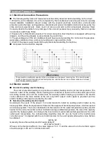
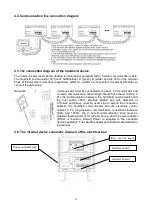
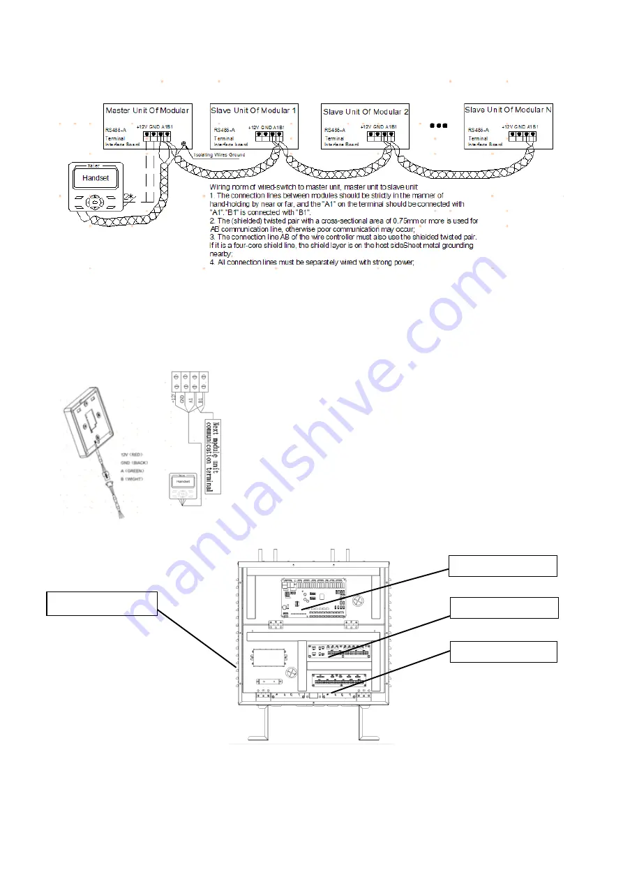
4.4.Communication line connection diagram
4.5.The connection diagram of the handheld device
The Communicator reserves the docking terminal and is equipped with a 5 meter communication cable.
The handheld communicator 12V (red), GND (black), A (green), B (white) and the 12V on the terminal
block of the electrical control box respectively. GND, A1, and B1 are connected. It is strictly forbidden to
connect the wrong line.
Remarks:
1
Communicator must be connected to the host; 2 Communicator and
modular communication cable length should not exceed 1000m; 3
For the communication between the handheld communicator and
the host within 300m, shielded twisted pair with diameter of
0.75mm2 and above must be used. Line to extend the connection
between the handheld communicator and the electronic control
cabinet; 4 For long-distance communication connections between
300m and 1000m, the A and B communication lines must be
shielded twisted pairs of 1mm2 and above, and the power adapter
(DC12) is required. Output) Power is supplied to the handheld
device separately. The specific adapter specifications are detailed in
the manual.
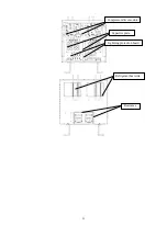
4.6. The internal device schematic diagram of the electrical box
Power terminal block
Main control board
Interface board 1
Interface board 2
Summary of Contents for CA0065EANR
Page 8: ...5 1 2 Main components of the unit ...
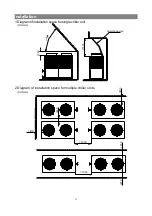
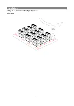
Page 15: ...12 Installation 3 Diagram of arrangement of multiple chiller units Unit mm ...
Page 37: ......
Page 38: ......
Page 39: ......
Page 40: ......

