background image

- 14 -

Service Manual

Order No. TL1206S003V1.1

Issue

Rev.

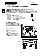
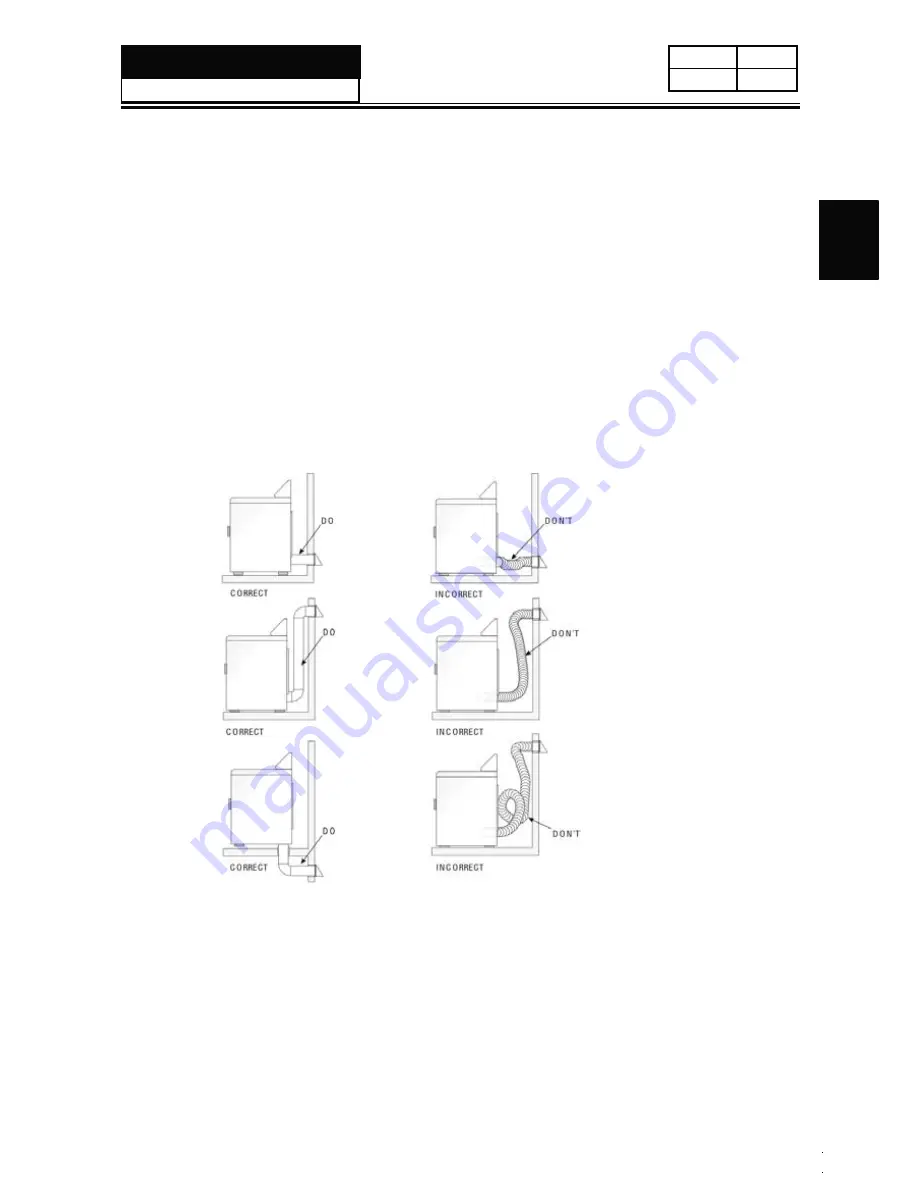
1. Dryer MUST be exhausted outside (outdoors, not beneath the manufactured 

home) using metal ducting that will not support combustion. Metal ducting must 

be 4 inch (10.16 cm) in diameter with no obstructions. Rigid metal duct 

is preferred. 

2. If dryer is exhausted through the floor and area beneath the manufactured 

home is enclosed, the exhaust system MUST terminate outside the enclosure 

with the termination securely fastened to the mobile home structure. 

3. When installing a gas dryer into a manufactured home, a provision must be 

made for outside make up air. This provision is to be not less than twice the 

area of the dryer exhaust outlet. 

4. This dryer MUST be fastened to the floor using P/N 0030807899 

Manufactured Home Installation Kit. Follow the instructions supplied with 

the kit. 

5. Refer to previous sections for other important venting requirements. 

6. Installation must conform to current Manufactured Home Construction & Safety 

Standard (which is a Federal Regulation Title 24 CFR-Part 32-80) or when 

such standard is not applicable, with American National Standard for Mobile 

Homes. In Canada, the CSA Z240 is applicable.

7-5. 

Manufacation (mobile) home installation

Gas dryers are equipped with a factory installed three-prong 15 Amps ~120 
Volts (grounding) plug for your protection against shock hazard and should be 
plugged directly into a properly grounded three-prong receptacle. Do not cut 
or remove the grounding prong from this plug.

7-6. ELECTRICAL INSTALLATION

7

Summary of Contents for GDG480BW

Page 1: ...Gas Dryer Model No GDG480BW Order No TL1206S003V1 1 2008 Haier Washing Machine ...

Page 2: ... Installation 13 1 4 Function indication symbols 3 7 1 Remove packing materials 7 7 Manufactured Mobile Home Hold Down Kit 7 9 Gas connections 7 10 Connecting to the Gas Supply 7 8 Natural Gas to LP Gas Conversion Kit 7 2 Adjusting the Dryer 7 4 Installation in Alcove or Closet 7 6 Electrical Installation 7 5 Manufacation mobile home installation 7 3 Location of your dryer Chapter 8 Wiring circuit...

Page 3: ... the service places serviced or not And be sure safety of that 1 3 Caution and Warning symbols Most important thing is to list up the potential hazard or risk for the service personnel to open the units and disassemble the units For example we need to describe properly how to avoid the possibility to get electrical shock from the live power supply or charged electrical parts even the power is off ...

Page 4: ...yer in its final position you can level your dryer Leveling legs can be adjusted by turning them clockwise to raise your dryer or by turning them counterclockwise to lower your dryer 3 End of Cycle Signal At the end of the dry cycle an audible signal will beep to alert you that the dryer has completed drying the load 4 Wrinkle Saver At the end of the dry cycle the dryer will automatically go into ...

Page 5: ...oor End of Cycle Signal Easy Access Lint Filter Interior Drum Light Dryer Rack Auto Dry Cycles 4 Heavy Normal Delicates Time Dry 10 30 60 90 Wrinkle Saver Works upto I hr after every cycle Exhaust Vents Rear Only Leveling Legs 4 LP Conversion Kit Serviceable Front Heating Element watts 20 000BTU Unit Dimensions In Width 27 686mm Depth With Door Close 28 3 718mm Depth With Door Open 50 6 1285mm Hei...

Page 6: ...ub stains as they give off vapors which could ignite or explode 3 Do not allow children to play on or in the appliance Close supervision of children is necessary when the appliance is used near children 4 Before the appliance is removed from service or discarded remove the door to the drying compartment 5 Do not reach into the appliance if the drum is moving 6 Do not install or store this applianc...

Page 7: ...r electrical power source Risk of Fire WARNING 1 Clothes dryer installation must be performed by a qualified installer 2 Install the clothes dryer according to the manufacturer s instructions and local codes 3 Do not install a clothes dryer with flexible plastic venting materials If flexible metal foil type duct is installed it must be of a specific type identified by the appliance manufacturer as...

Page 8: ...nd into the interior of the duct 7 Do not allow combustible material clothing draperies curtains paper etc to come in contact with exhaust system Explosion hazard Do not install the dryer where gasoline or other flammables are kept or stored If the dryer is installed in a garage it must be a minimum of 18 inches 45 7cm above the floor Failure to do so can result in death explosion fire or burns Ex...

Page 9: ...lation must conform with the National Fuel Gas Code ANSI Z223 1 latest edition or in Canada the current CAN CGA B149 1 2 The gas supply line should be 1 2 inch 1 27cm pipe 3 If codes allow flexible metal tubing may be used to connect your dryer to the gas supply line The tubing MUST be constructed of stainless steel or plastic coated brass 4 The gas supply line MUST have an individual manual shuto...

Page 10: ...ne 1 3 4 5 2 Start Pause Button 4 Push to shart after selecting the dry cycle and seting the temperature Push once to pause Push again to start after pushing Cycle Progress 5 This indicates the process the cycle is currently in At the end of cycyle the dryer will automatically go in the wrinkle saves mode Here the dryer tub will tumble periodically for 1 hour after the dry cycle is completed To st...

Page 11: ...id entanglement and ensure easy removal Make sure the power socket is reliably grounded The grounding terminal should not be connected to gas or tap water pipelines Make sure exhaust duct has been properly connected Make sure lint filter is clean and properly installed If lint filter is not in place tumbling items could enter the exhaust system and cause damage to the dryer Note Applies to Auto Dr...

Page 12: ...Chapter 6 Appearance brief introduction 12 Service Manual Order No TL1206S003V1 1 Issue Rev 6 1 Name of parts 6 2 Net dimension 6 ...

Page 13: ...n and ventilation air 3 On carpet floor must be solid with a maximum slope of 1inch 2 54 cm Any floor unevenness should be corrected with leveling legs located on the bottom of the dryer 7 4 Installation in Alcove or Closet 1 DO NOT install your dryer in a closet with a solid door 2 A dryer installed in a bedroom bathroom alcove or closet MUST be exhausted outdoors 3 No other fuel burning applianc...

Page 14: ...area of the dryer exhaust outlet 4 This dryer MUST be fastened to the floor using P N 0030807899 Manufactured Home Installation Kit Follow the instructions supplied with the kit 5 Refer to previous sections for other important venting requirements 6 Installation must conform to current Manufactured Home Construction Safety Standard which is a Federal Regulation Title 24 CFR Part 32 80 or when such...

Page 15: ...lace dryer in location where it is to be installed Refer to the User Manual for information about locating your dryer NOTE Allow adequate space between the back of dryer and the wall to ensure proper exhaust connection 2 Level the dryer by adjusting the leveling feet Check with a carpenters level 3 Assemble the exhaust duct to the dryer NOTE The exhaust duct MUST NOT terminate under the manufactur...

Page 16: ...Orientation 11 0 in 280mm to edge of bracket TOP VIEW 11 0 in 280mm to edge of bracket 1 0 in 25mm to edge of bracket 0030101225 0030101240 THIS CONVERSION KIT SHALL BE INSTALLED BY A QUALIFIED SERVICE AGENCY IN ACCORDANCE WITH THE MANUFACTURER S INSTRUCTIONS AND ALL APPLICABLE CODES AND REQUIREMENTS OF THE AUTHORITY HAVING JURISDICTION THE INFORMATION IN THESE INSTRUCTIONS MUST BE FOLLOWED TO MIN...

Page 17: ...030502705A LP Gas Conversion Service Sticker French 1 0030502704 LP Gas Valve Sticker English 1 0030502704A LP Gas Valve Sticker French 1 0030502715 Instructions Gas input 20 000 BTU HR Before converting the dryer to LP Gas verify that the incoming gas supply line is equipped with a pressure regulator located ahead of the dryer that will maintain the gas supply to the dryer at 12 5 1 5 W C 31 8 3 ...

Page 18: ... from the top of the gas valve Install the new regulator blocking plug finger tight then tighten it no more than 1 8 turn to seal it Figure 5 12 Apply No 0030502704 LP Gas Valve Converted Sticker over the existing valve label Figure 5 In Canada apply No 0030502704A French 13 Sign and date one of the No 0030502705 LP Gas Service Stickers and apply it adjacent to the exiting dataplate on the rear of...

Page 19: ...e drum belt and reinstall the vent panel 27 Connect electrical service and turn on gas supply to the dryer Figure 6 Presure Tap Plug 12 5 1 5 W C 31 8 3 8cm W C U Tube Manometer 7 9 Gas connections NOTE DO NOT connect the dryer to L P gas service without converting the gas valve An L P Conversion Kit must be installed by a qualified gas technician 1 Remove the shipping cap from gas pipe at the rea...

Page 20: ... the dryer is turned on the safety switch will shut the burner off If this happens turn the dryer to Off and wait 5 minutes before making another attempt to light NOTE Follow instructons supplied with kit A Connect female 3 8 NPT elbow to gas inlet on dryer Then connect 3 8 flare union adapter to female elbow IMPORTANT To prevent the inlet from twisting please use a pipe wrench to secure the dryer...

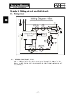
Page 21: ...ellow White White Red Black Brown Blue Yellow Green Thermal Limiter Computer Program Controller Door Switch Gas Valve Igniter Radiant Sensor Cycling Thermostat High Limit Thermostat Back up Thermostat Belt Switch Moter Display self check Press the buttons of Temp and Start pause at the same time then all the LED ON 05s OFF 0 5s and signal 0 5s after 3 times repeats dryer will automatically off ...

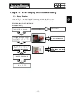
Page 22: ...not closed Troubleshooting Confirm that the door is closed Y Close the door N N well Y Cut off the power Check if the wire connecting door switch and PCB is disconnection Connect the wire properly Check if the Door switch is good Well the resistence is 0Ω Broken he resistence is infinite broken Replace the door switch and make sure wire is connected properly Check if the wire unit is good 9 Y Repl...

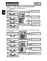
Page 23: ...ng wire unit and PCB is disconnection Replace the powerline and the wire unit 9 2 2 The computer is power on and display rightˈbut the dryer no action Troubleshooting Cut off the power Check if the belt is break off or the connecting of the motor ǃbelt switch is loose Replace the belt or connect the wire properly Check if the tensive arm unit is installed well Reinstall the tensive wheel unit and ...

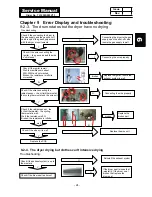
Page 24: ...s shut off valve is open the gas supply accord with the dryer s requirements Check if the wire connecting the igniter ǃthe gas valve and the wire unit is loose Check if the ignitor is well Well the resistance is about 50Ω 500Ω and not cracked Broken the resistance is infinite or cracked Check if the wire connecting the radiant sensorǃthe hi limit thermostatǃ the cycling thermostat and the wire uni...

Page 25: ...ng Check if is there gratings between the impeller and the worm shell Switch on the power push down the start button If the noise from the tensive arm unit or the belt Check if some screw become flexible Check if the drum can touch something N N Reinstall the tensive arm unit or replace the tensive arm unit and the belt Reinstall them and liet the drum can t touch anything Replace the worm shell 2...

Page 26: ...Printed in China Sincere Forever Haier Group Haier Industrial Park No 1 Haier Road 266101 Qingdao China http www haier com ...

Reviews: