background image

Page  26

31-5000734   Rev. 0

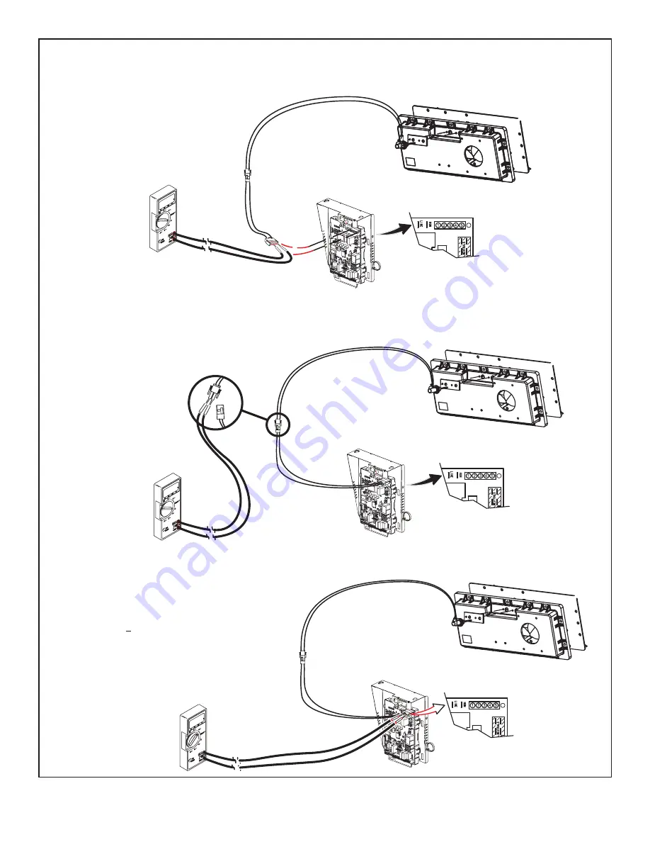
Ignitor Check Out

(exploded view for clarity)

Test 1

Meter

(set to ohms)

Remove 5-pin plug from control

Check ohms reading across terminals 1and 5

Ohm value should be between 39 - 70.

Integrated control detail

Test 2

Seperate the 2-pin jack plug near the manifold

and check resistance of the ignitor. If the reading

is correct, then then there is a problem with the

wiring between the jack plug and control. If the

reading is not correct the issue is the ignitor.

Meter

(set to ohms)

Test 3

Insert meter probes into the terminals 1 and 5. (Use small

diameter probes in order to not damage plug). Check

voltage during 20 second warm up period. Voltage should

read 120 volts + 10%. If voltage is above these values,

check for correct supply voltage to furnace.

Integrated control detail

Integrated control detail

Meter

(set to AC volts)

Figure 14.  

Summary of Contents for GE NF80XV Series

Page 1: ...31 5000734 Rev 0 11 22 GEA NF80XV 80 Two Stage Variable Speed Ultra Low NOx Gas Furnace Service Manual READ CAREFULLY KEEP THESE INSTRUCTIONS ...

Page 2: ... are approved for installations up 7500 ft and factory equipped for use with natural gas only NF80XV model units are equipped with a two stage variable speed integrated control NF80XV unit meets the California Nitrogen Oxides NOx Standards and California Seasonal Efficiency requirements All units use a redundant gas valve to assure safety shut off as required by C S A All specifications in this ma...

Page 3: ...F80X060V3A 60 000 48 000 80 3 Tons 1 2 120 60 1 15 7 7 40 112 NF80X080V4B 80 000 64 000 80 4 Ton 1 2 120 60 1 20 12 8 40 138 NF80X100V5C 100 000 80 000 80 5 Ton 1 2 120 60 1 20 12 8 40 161 NOTE For vent length and clearances to combustibles please reference installation instructions Accessory List Catalog Number Description Return Air Base 68W61 Return Air Base 14 5 Inch A Width 68W62 Return Air B...

Page 4: ...24 1350 1500 18 1270 1420 12 1200 1340 6 1130 1270 Factory Default 1060 1190 6 970 1130 12 880 1025 18 845 950 COOLING 1 Cooling Speed DIP Switch Settings First Stage Cooling Speed cfm Second Stage Cooling Speed cfm Low Medium Low Medium High 2 High Low Medium Low Medium High 2 High 640 870 1030 1200 1020 1310 1535 1750 Factory Default 590 770 925 1100 935 1200 1400 1600 545 635 750 960 815 1080 1...

Page 5: ...m High 2 High Low Medium Low Medium High 2 High 1060 1220 1330 1565 1535 1710 1910 2210 Factory Default 970 1075 1180 1430 1400 1565 1715 2015 875 980 1070 1255 1260 1400 1560 1815 1 Cooling and heating speeds are based on a combination of DIP switch settings on the furnace control Refer to Installation Instructions for specific DIP Switch Settings 2 Factory default setting NOTES The effect of sta...

Page 6: ...00734 Rev 0 Parts Arrangement Heat Exchanger Combustion Air Inducer Gas Valve Air Intake Pipe Control Box includes two stage integrated control transformer and circuit breaker Blower Assembly Access Panel Figure 1 ...

Page 7: ...f the current exceeds this limit the breaker will trip and all unit operation will shutdown The breaker can be manually reset by pressing the button on the face See Figure 3 CIRCUIT BREAKER CB8 PRESS TO RESET Figure 3 Shock hazard Disconnect power before servicing Integrated control is not field repairable If control is inoperable simply replace entire control Can cause injury or death Unsafe oper...

Page 8: ... is factory set in the OFF position for use with a two stage thermostat Move the DIP switch to ON for use with a single stage thermostat While in the single stage thermostat mode the burners will always fire on first stage heat The combustion air inducer will operate on low speed and indoor blower will operate on low heat speed The unit will switch to second stage heat after a recognition period D...

Page 9: ...D STAGE THERMOSTAT W1 HEAT DEMAND FROM 1ST STAGE THERMOSTAT R CLASS 2 VOLTAGE TO THERMOSTAT G MANUAL FAN FROM THERMOSTAT C THERMOSTAT SIGNAL GROUND CONNECTED TO TRANSFORMER GRD TR CHASSIS GROUND GRD Y1 THERMOSTAT 1ST STAGE COOL SIGNAL Y2 THERMOSTAT 2ND STAGE COOL SIGNAL O THERMOSTAT SIGNAL TO HEAT PUMP REVERSING VALVE L NOT USED DH NOT USED HUM UNPOWERED NORMALLY OPEN DRY CONTACTS XMFR 120 VAC OUT...

Page 10: ...N B OFF 82 100 OFF OPTION C OFF 100 100 OFF OPTION D OFF 100 OFF DEFAULT 10 10 HIGH SPEED MEDIUM HIGH SPEED MEDIUM LOW SPEED LOW SPEED 7 PROTECTIVE PLASTIC FILM ON DIP SWITCHES MAY BE REMOVED FOR EASE IN SETTING OF DIP SW CUT ON BOARD LINK SOLDER TRACE COMPLETELY THROUGH BOTH LAYERS ON THE CONTROL BOARD LINKS CUT IN ERROR INSTALL A JUMPER ON THE APPROPRIATE TERMINALS ON THE TERMINAL STRIP 1 9 10 1...

Page 11: ...access the flame signal mode The integrated control will display the flame current on 7 segment LED in in micro amps uA Flame signal mode is exited after any of the following Power is reset Pressing and holding push button until 3 horizontal lines are displayed 10 minutes after entering the flame sense mode Program Unit Capacity Size Mode After the P is selected by releasing the push button the in...

Page 12: ...ovide proper earth ground System resumes normal operation 5 seconds after fault recovered E113 High line voltage Line Voltage high Voltage higher than nameplate rating Provide power voltage within proper range System resumes normal operation 5 seconds after fault recovered E114 Line voltage frequency out of range No 60 Hertz power Check voltage and line power frequency Correct voltage and frequenc...

Page 13: ...e control relay contact shorted Check wiring on control and gas valve If wiring is correct replace control E206 Gas valve second stage relay failure Furnace will operate on 1st stage for remainder of the heating demand Will clear after fault recovered If unable to operate 2nd stage replace control E207 Hot surface igniter sensed open Refer to troubleshooting Measure resistance of hot surface ignit...

Page 14: ...No flame current sensed Check for proper gas flow Ensure that igniter is lighting burners Check flame sensor current Clears when heat call finishes successfully E271 Soft lockout Exceeded maximum number of retries Last retry failed due to the pressure switch opening Check pressure inches w c of low pressure switch closing on heat call Measure operating pressure inches w c Inspect vent and combusti...

Page 15: ...ed or repair add duct 2 stage controls will reduce firing rate to 1 stage Clears when heat call finished successfully E312 Restricted airflow in cooling or continuous fan mode is lower than CFM setting Warning Only Restricted airflow Indoor blower is running at a reduced CFM Cutback Mode The variable speed motor has preset speed and torque limiters to protect the motor from damage caused by operat...

Page 16: ...ttings provide lower supply air temperatures shorter settings provide higher supply air temperatures Table 5 provides the blower off timings that will result from different switch settings Blower Off Delay Seconds Switch 3 Switch 4 60 On Off 90 factory Off Off 120 Off On 180 On On Table 5 Blower Off Delay Switch Settings Indoor Blower Operation DIP Switch Settings Switches 5 and 6 Cooling Mode Blo...

Page 17: ...OMPRESSOR DEMAND Ramping Option D Motor runs at 100 until demand is satisfied Once demand is met motor ramps down to stop OFF OFF 100 CFM COMPRESSOR DEMAND Switches 11 12 and 13 Heating Mode Blower Speed The switches are factory set to the OFF position which provides factory default heat speed Refer to Table 9 for switches 11 12 and 13 that provided the corresponding increases or decrease to both ...

Page 18: ...be cut if two stage cooling will be used If the Y1 to Y2 link is not cut the outdoor unit will operate in second stage cooling only Operating Sequence System Demand System Response System Condition Step Thermostat Demand Relative Humidity Compressor Blower CFM cool Comments Y1 O G W1 Status D NO CALL FOR DEHUMIDIFICATION Normal Operation 1 On On On Acceptable 24 VAC High 100 Compressor and indoor ...

Page 19: ...point ROOM THERMOSTAT CALLS FOR FIRST AND SECOND STAGE COOLING BASIC MODE only active on a Y1 thermostat demand Normal Operation 1 On On On On Acceptable 24 VAC High 100 Thermostat energizes Y2 and de energizes D on a call for de humidification Dehumidification Call 2 On On On On Demand 0 VAC High 70 PRECISION MODE operates independent of a Y1 thermostat demand Normal Operation 1 On On On Acceptab...

Page 20: ...ditions inside the motor such as motor workload BLOWER MOTOR COMPONENTS STATOR WINDINGS BEARING ROTOR Figure 7 The controller uses sensing devices to sense what position the rotor is in at any given time By sensing the position of the rotor and then switching the motor windings on and off in sequence the rotor shaft turns the blower All NF80XV blower motors use single phase power An external run c...

Page 21: ... the unit before attempting to service motor Disconnect power from unit and wait at least five minutes to allow capacitors to discharge before attempting to service motor Failure to wait may cause personal injury or death DANGER Power Choke L13 A choke coil is used on NF80XV 4 and 5 ton units equipped with 1 hp motors The choke is located on the blower housing and is used to suppress transient cur...

Page 22: ...J48 5 Pin Line Voltage Connector J49 4 Pin Control Connector J48 5 Pin J49 4 Pin Figure 8 BLOWER B3 HARNESS CONNECTORS MOTOR with INTEGRATED CONTROLLER SHAFT P49 4 Pin P48 5 Pin P48 5 Pin P49 4 Pin J48 Connector installed on motor P49 4 Pin 120v 0 240v 5 4 3 2 1 J48 Connector 24v Transformer J49 Connector Figure 9 ...

Page 23: ...e 10 TEST A Measure the resistance between each of the three motor leads 3 pin plug and the unpainted part of the end shield If the winding resistance to ground is 100k ohms replace the motor and control module If the resistance to ground is 100k the motor windings are fine Proceed to Test B Test A Figure 11 TEST B Use an ohmmeter to measure the motor phase to phase resistance by checking these co...

Page 24: ...rminals energizes the valve Inlet and outlet pressure taps are located on the valve A regulator adjustment screw is located on the valve Thermal Switch The auto reset switch is located on the front of the intake air elbow The switch will safely shut the unit down if excessive temperatures are detected See Figure 13 When the switch senses excessive temperature the circuit breaks and the ignition co...

Page 25: ...ge 25 31 5000734 Rev 0 HEATING COMPONENTS Air Gas Plenum Burner Gasket Orifice Housing Gas Valve Air Orifice Sensor Ignitor Gas Orifice Thermal Switch location Intake Air Screen Intake Air Elbow Figure 13 ...

Page 26: ...the reading is correct then then there is a problem with the wiring between the jack plug and control If the reading is not correct the issue is the ignitor Meter set to ohms Test 3 Insert meter probes into the terminals 1 and 5 Use small diameter probes in order to not damage plug Check voltage during 20 second warm up period Voltage should read 120 volts 10 If voltage is above these values check...

Page 27: ...ation the switch senses a loss of pressure difference and opens the circuit to the furnace control and gas valve COMBUSTION AIR PRESSURE SWITCH Positive to air intake pipe Negative to air intake elbow Figure 15 NOTE The switch is factory set and is not field adjustable It is a safety shut down control in the furnace and must not be by passed for any reason If switch is closed or bypassed the contr...

Page 28: ...t for blockages 10 Is pressure switch closed Obstructed flue will cause unit to shut off at pressure switch Check flue and outlet for blockages 11 Are flame rollout switches tripped If flame rollout switches are tripped call the service technician for inspection Safety or Emergency Shutdown Turn off unit power Close manual and main gas valves Extended Period Shutdown Turn off thermostat or set to ...

Page 29: ... shut off valve between the manometer and the gas tap to permit shut off of gas pressure to the manometer IMPORTANT Rate Check Manifold Pressure Measurement To correctly measure manifold pressure follow the steps below 1 Remove the threaded plug from the outlet side of the gas valve and install a field provided barbed fitting Connect measuring device connection to barbed fitting to measure manifol...

Page 30: ...ral 1 cu ft Dial 2 cu ft Dial 060 60 120 080 45 90 100 36 72 Natural 1000 btu cu ft Table 18 Gas Meter Clocking Chart High Altitude Units may be installed at altitudes up to 7 500 ft above sea level See Table 17 for de rate manifold values 60K natural gas units installed at altitude of 4 501 7 500 feet require a pressure switch change which can be ordered separately Table 19 lists pressure switch ...

Page 31: ...MPERATURE RISE Supply Duct Temperature ________ Return Duct Temperature _ _____ Temperature Rise ________ Figure 18 External Static Pressure 1 Tap locations shown in Figure 19 2 Punch a 1 4 diameter hole in supply and return air plenums Insert manometer hose flush with inside edge of hole or insulation Seal around the hose with permagum Connect the zero end of the manometer to the discharge supply...

Page 32: ...nducer and clean if necessary 8 Evaluate the heat exchanger integrity by inspecting the heat exchanger per the AHRI heat exchanger inspection procedure This procedure can be viewed at GEAppliances com 9 Ensure sufficient combustion air is available to the furnace Fresh air grilles and louvers on the unit and in the room where the furnace is installed must be properly sized open and unobstructed to...

Page 33: ...all burner plate 10 To clean the combustion air inducer visually inspect and using a wire brush clean where necessary Use compressed air to clean off debris and any rust 11 Reinstall heat exchanger in vestibule Replace the five screws in the cabinet from step 7 if removed 12 Reinstall the air fuel plenum and air intake assembly Make note of the numbered sequence when re installing the air fuel ple...

Page 34: ... STAGE position Electric Shock Hazard Can cause injury or death Unit must be properly grounded in accordance with national and local codes re attempting to service motor Failure to wait may cause personal injury or death WARNING Fire Hazard Use of aluminum wire with this product may result in a fire causing property damage severe injury or death Use copper wire only with this product WARNING Failu...

Page 35: ...Page 35 31 5000734 Rev 0 Figure 22 Schematic Wiring Diagram ...

Page 36: ...Page 36 31 5000734 Rev 0 060 3A 080 4B 100 5C DISCHARGE AND OUTDOOR AIR TERMINALS NOT USED DH TERMINAL NOT USED THERMOSTAT CONNECTIONS ARE FOR 24V SYSTEM ONLY Figure 23 ...

Page 37: ...fire heat is satisfied the gas valve is de energized and the field selected indoor blower off delay begins The combustion air inducer begins a 5 second post purge period 9 When the combustion air post purge period is complete the inducer the HUM contacts as well as the 120V ACC terminals are de energized The indoor blower is de energized at the end of the off delay Applications Using A Single Stag...

Page 38: ... on all units H 1 Heat 2 Cool NOTE Use DIP switch 3 to set sceond stage heat ON delay OFF 7 minutes ON 12 minutes ON Cut Intact Intact T STAT FURNACE TERM STRIP OUTDOOR UNIT Not required on all units H 1 Heat 2 Cool with t stat with dehumidification mode NOTE Use DIP switch 3 to set sceond stage heat ON delay OFF 7 minutes ON 12 minutes ON Cut Cut Intact T STAT FURNACE TERM STRIP OUTDOOR UNIT o No...

Page 39: ...E TERM STRIP OUTDOOR UNIT Not required on all units H 2 Heat 2 Cool with t stat with dehumidification mode OFF Cut Cut Intact T STAT FURNACE TERM STRIP OUTDOOR UNIT o Not required on all units H 2 Heat 1 Cool OFF Intact Intact Intact T STAT FURNACE TERM STRIP OUTDOOR UNIT Not required on all units H NOTE Do NOT make a wire connection between the room thermostat L terminal and the L terminal of the...

Page 40: ...age gas heat control OFF Intact Intact Cut T STAT FURNACE TERM STRIP HEAT PUMP 67M41 Y H L Y2 D B L Y2 T T outdoor sensor H Dual Fuel Two Stage Heat Pump Thermostat w dual fuel capabilities Capable of 2 stage gas heat control OFF Cut Intact Cut FURNACE TERM STRIP HEAT PUMP out blue 67M41 H L Y2 D B L Y2 T T outdoor sensor T STAT Y2 H NOTE Do NOT make a wire connection between the room thermostat L...

Page 41: ... dehumidification mode OFF Intact Cut Cut T STAT FURNACE TERM STRIP HEAT PUMP 67M41 Y H L Y2 D B L Y2 T T outdoor sensor H Dual Fuel Two Stage Heat Pump Thermostat w dual fuel capabilities Capable of 2 stage gas heat control with dehumidification mode OFF Cut Cut Cut T STAT FURNACE TERM STRIP HEAT PUMP 67M41 H L Y2 D B L Y2 T T outdoor sensor Y2 out blue Y2 H NOTE Do NOT make a wire connection bet...

Page 42: ...hout storing unit size code If this happens programming function must be repeated Verify that the selected unit size code is correct and stored in non volatile memory by cycling the 24 volt power to the furnace control At 24 volt power up of the furnace control the 7 segment LED will display a unit size code If three horizontal bars display the board does not recognize the unit size code The progr...

Page 43: ... AFTER POST PURGE HARD LOCKOUT ERROR CODE FLASHES YES YES YES 1 2 1 LOW PRESSURE SWITCH OPENS 1 2 HARD LOCKOUT REQUIRES THERMOSTAT RESET OR CYCLING OF POWER TO RESET THE LOCKOUT 3 IN CASE HIGH SPEED INDUCER IS RUNNING AT THE TIME THE GAS VALVE GETS ENERGIZED 2ND STAGE GAS VALVE IS ENERGIZED INSTEAD OF 1ST STAGE 20 SECONDS AFTER FLAME IS SENSED INDUCER SWITCHES TO LOW SPEED AND GAS VALVE SWITCHES T...

Page 44: ... YES CALL FOR HEAT SATISFIED INDUCER SWITCHED TO HIGH SPEED SINGLE STAGE THERMOSTAT 2 STAGE THERMOSTAT NO INDUCER SWITCHED TO LOW SPEED 5 MINUTE DELAY ERROR CODE FLASHES HIGH PRESSURE SWITCH CLOSED WITHIN 10 SECONDS 2ND STAGE ON DELAY EXPIRED CALL FOR 2ND STAGE HEAT HIGH FIRE 2 3 1 2 3 1 2 3 YES YES CALL FOR SECOND STAGE HEAT RECOGNITION DELAY 30 SECONDS EXPIRED INDOOR BLOWER ENERGIZED ON HIGH HEA...

Page 45: ...E ENERGIZE 2ND STAGE GAS VALVE INDUCER SPEED SWITCHED TO LOW SPEED 1 2 3 1ST STAGE HEAT 1ST STAGE CALL FOR HEAT SATISFIED NO YES GAS VALVE DE ENERGIZED INDUCER OFF AFTER 5 SECOND POST PURGE CALL FOR HEAT SATISFIED FIRST STAGE HEAT SECOND STAGE HEAT INDOOR BLOWER SWITCHED TO LOW HEAT SPEED INDOOR BLOWER OFF AFTER FIELD SELECTABLE OFF DELAY Figure 26 Heating Sequence of Operation Continued ...

Page 46: ...FILE IS SELECTED USING THE 1 1 2 2 1 1 1 2 2 DE ENERGIZE 1ST STAGE COOLING CONTACTOR COMPRESSOR FAN 2ND STAGE COOLING REQUEST STILL ACTIVE COOLING REQUEST STILL ACTIVE CALL FOR COOLING WAIT FOR COMPRESSOR TIMED OFF DELAY TO EXPIRE INDOOR BLOWER 2 SECOND ON DELAY YES 1ST STAGE DE ENERGIZE INDOOR BLOWER INDOOR BLOWER LOW COOLING MODE AND HIGH COOLING MODE HAVE SPECIFIC ON OFF ENERGIZE INDOOR BLOWER ...

Page 47: ...OLING RECEIVED GO TO CALL FOR 1ST STAGE HEAT YES GO TO CALL FOR COOLING 1 1 1 4 YES NO CALL FOR FAN INDOOR BLOWER ON CONTINUOUS FAN SPEED MAINTAIN INDOOR BLOWER AT CONTINUOUS FAN MAINTAIN INDOOR BLOWER AT CONTINUOUS FAN INDOOR BLOWER OFF DE ENERGIZE INDOOR BLOWER Figure 28 Continuous Fan Sequence of Operation ...

Page 48: ...Printed in the U S A All specifications and illustrations subject to change without notice and without incurring obligations ...

Reviews: