507962-01G / 31-5000654
Page 11 of 51
Issue 2149
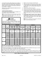
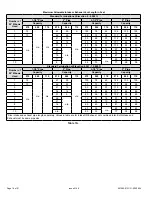
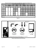
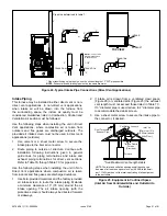
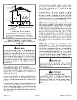
Figure 14.
Downflow Application Installation
Clearances
Top
0
* Front
0
Back
0
Sides
0†
Vent
0
Floor
NC‡
* Front clearance in alcove installation must be 24 in. (610
mm). Maintain a minimum of 24 in. (610 mm) for front service
access.
† Allow proper clearances to accommodate condensate trap.
‡ The furnace may be installed on a combustible wood floor if
an optional additive base is installed between the furnace and
the combustible floor.
Installation on Non-Combustible Flooring
1.
Cut floor opening keeping in mind clearances listed
on unit rating plate. Also keep in mind gas supply
connections, electrical supply, flue and air intake
connections and sufficient installation and servicing
clearances. See Table 1 for correct floor opening size.
2. Flange warm air plenum and lower the plenum into the
opening.
3. Set the unit over the plenum and seal the plenum to
the unit.
4. Ensure that the seal is adequate.
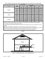
Table 1.
Non-Combustible Floor Opening Size
Cabinet Width
Front to Rear
Side to Side
in.
mm
in.
mm
B cabinet (17.5”)
19-3/4
502
16-5/8
422
C cabinet (21”)
20-1/8
511
NOTE
: Floor opening dimensions listed are 1/4 in. (6 mm)
larger than the unit opening. See dimension drawing on Page
Figure 15.
Installation on Combustible Flooring
1.
When unit is installed on a combustible floor, a
downflow combustible flooring base must be installed
between the furnace and the floor. The base must be
ordered separately. See Table 2 for opening size to
cut in floor.
The furnace and combustible flooring base shall not be
installed directly on carpeting, tile, or other combustible
material other than wood flooring.
CAUTION
Table 2.
Combustible Flooring Base Opening Size
Cabinet
Width
Catalog
Number
Front to Rear
Side to Side
in.
mm
in.
mm
B cabinet
(17.5”)
11M60
22
559
18-3/4
476
C cabinet
(21”)
11M61
22-3/4
578
Figure 16.


