507962-01G / 31-5000654
Page 12 of 51
Issue 2149
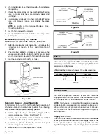
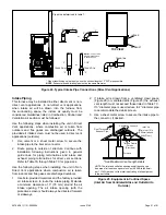
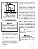
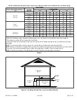
Figure 18.
Figure 19.
Filters
This unit is not equipped with a filter or rack. A field provided
filter is required for the unit to operate properly. Table 3 lists
recommended filter sizes.
A filter must be in place whenever the unit is operating.
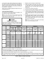
Table 3.
Furnace Cabinet Width
Filter Size
17-1/2”
16 x 25 x 1 (1)
21”
Duct System
Use industry-approved standards to size and install the
supply and return air duct system. This will result in a quiet
and low-static system that has uniform air distribution.
NOTE:
This furnace is not certified for operation in heating
mode (indoor blower operating at selected heating speed)
with an external static pressure which exceeds 0.8 inches
w.c. Operation at these conditions may result in improper
limit operation.
Supply Air Plenum
If the furnace is installed without a cooling coil, a removable
access panel should be installed in the supply air duct. The
access panel should be large enough to permit inspection
(by reflected light) of the heat exchanger for leaks after the
2.
After opening is cut, set the combustible flooring base
into opening.
3.
Check fiberglass strips on the combustible flooring
base to make sure they are properly glued and
positioned.
4.
Lower supply air plenum into the combustible flooring
base until plenum flanges seal against fiberglass
strips.
NOTE:
Be careful not to damage fiberglass strips.
Check for a tight seal.
5. Set the furnace over the plenum.
6. Ensure that the seal between the furnace and plenum
is adequate.
Installation on Cooling Coil Cabinet
NOTE:
Downflow combustible flooring kit is not used.
1.
Refer to reverse-flow coil installation instructions for
correctly sized opening in floor and installation of
cabinet.
2. When cooling cabinet is in place, set and secure the
furnace according to the instructions that are provided
with the cooling coil. Secure the furnace to the cabinet.
3. Seal the cabinet and check for air leaks.
Figure 17.
Return Air Opening - Downflow Units
Return air may be brought in only through the top opening of
a furnace installed in the downflow position. The following
steps should be taken when installing plenum:
1.
Bottom edge of plenum should be flanged with a
hemmed edge (see Figure 18 or Figure 19).
2. Sealing strips should be used to ensure an airtight
seal between the cabinet and the plenum.
3. In all cases, plenum should be secured to top of
furnace using sheet metal screws.
4. Make certain that an adequate seal is made.


