background image

Manuale di Installazione e Manutenzione Recuperatori di Calore - 

Heat Recovery Units Installation, use and maintenance manual

pag. 16

4.1.2.4 Descrizione funzionamento

Il sistema di controllo PCU è un termostato in grado di comandare unità
di ventilazione a tre velocità, delle elettrovalvole 230V on/off ed una ser-
randa di bypass 230V on/off.
E’ inoltre dotato di un orologio interno con la possibilità di programmare
due fasce orarie di accensione/spegnimento e impostazione set point per
tre diversi tipi di fasce orarie: settimanale lunedì-venerdì (giorni da 1 a 5),
sabato (giorno 6) e domenica (giorno 7).

All’unità di controllo PCU vanno collegate due sonde di temperatura
esterna di tipo NTC 10k per la gestione della serranda di bypass.

Unitamente alla sonda interna al display, si hanno complessivamente tre
valori di temperatura visualizzati.

Il funzionamento delle ventilazione è regolato manualmente con apposi-
to tasto ventilazione (3) o automaticamente se selezionata la modalità
auto, in quest’ultimo caso le velocità cresceranno all’allontanarsi della
temperatura rilevata rispetto al set point impostato.

Le valvole riscaldamento/raffrescamento vengono attivate, a seconda
della modalità di funzionamento scelta, in funzione della differenza tra il
set point impostato e la sonda di regolazione scelta, che può essere la
sonda locale sul controllo o una delle due sonde esterne.

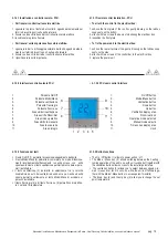
Durante il normale funzionamento sul display appare nell’area indicata
dal numero (7) la scritta ROOM, ed il valore di temperatura visualizzato
è quello della sonda locale a bordo dell’unità, se si preme e si tiene pre-
muto il tasto freccia su, la visualizzazione passa alla temperatura misu-
rata dalla sonda 1 (al posto dell’orologio appare la dicitura ntc1), rila-
sciando e premendo nuovamente freccia su, si ha la visualizzazione
della sonda 2 (dicitura ntc2).
La visualizzazione torna al valore di default dopo circa 5 secondi di man-
canza di pressione tasti.

Se si preme brevemente il tasto Modo/Menù si passa dalla modalità
riscaldamento/raffrescamento e viceversa.

L’azionamento dell’uscita di bypass avviene in modo differente a secon-
da della modalità di funzionamento:

-

Durante il funzionamento in riscaldamento si ha attivazione del

bypass se il valore rilevato da sonda 1 è inferiore al set point e se valo-
re rilevato dalla sonda S2 è superiore al set point
-

Durante il funzionamento in raffrescamento si ha attivazione del

bypass se il valore rilevato da sonda 1 è superiore al set point e se valo-
re rilevato dalla sonda S2 è inferiore al set point

Per rendere più selettiva l’azione del bypass si può settare un valore nel
menù costruttore in cui la sonda di temperatura deve essere
superiore/inferiore al set point di tale valore e non semplicemente supe-
riore/inferiore (vedasi paragrafo parametri installatore).

4.1.2.4 Description Operation

The PCU control system is a thermostat able to command of a three-
speed fan unit, the solenoid valves 230V on / off and a damper of 230V
bypass on / off.
It 'also equipped with an internal clock with the ability to program two time
slots on / off and setting the set point for three different time periods:
Weekly Monday-Friday (days 1 to 5), Saturday (day 6) and Sunday (day
7).

Two external temperature probes NTC 10k must be connected with the
PCU control unit for the management of the bypass damper.

Added the display internal probe, you will have a total of three displayed
temperature values.

The operation of the ventilation is adjusted manually with a special ven-
tilation button (3) or automatically when selected auto mode, in which
case the speed will grow to estrange the detected temperature from the
set point.

The heating / cooling valves are activated, depending on the operating
mode, as a function of the difference between the set point and the selec-
ted control probe, which can be the local probe on the control or one of
the two external probes.

During normal operation, the display area indicated by the number (7) the
written ROOM, and the temperature value displayed is that of the local
probe on the unit, if you press and hold the up arrow key, the display
changes to the temperature measured by the probe 1 (instead of the
clock appears NTC1 words), releasing and pressing arrow up, you have
the view of the probe 2 (NTC 2 words).
The display returns to the default value after about 5/2 of the lack of keys
pressure.

If you briefly press the Mode / Menu button switches between heating /
cooling mode and vice versa.

The bypass output drive takes place in a different way depending on the
mode of operation:

- During heating operation it has the bypass activated if the value mea-
sured by sensor 1 is below the set point and if the value detected by the
sensor S2 is greater than the set point
- During the cooling operation you will have the bypass activation if the
value measured by sensor 1 is greater than the set point and if the value
detected by the sensor S2 is below the set point

To make more selective the bypass action you can set a value in the
manufacturer menu in which the temperature probe must be higher /
lower than the set point of the value and no higher / lower simply (see
paragraph installer parameters).

4.1.2.5 Programmazione

Premendo a lungo il tasto Modo/Menù si passa in successione alle

seguenti funzionalità:

- Funzionamento notturno
- Modo funzionamento manuale o fasce orarie (da selezionare con i

tasti freccia)

- Programmazione orologio (minuti, ore, giorno attuale)
- Programmazione fasce orarie

Il passaggio da una funzionalità alla successiva è evidenziato dai diversi

simboli che iniziano a lampeggiare sul display.

Per modificare i parametri della relativa programmazione utilizzare i tasti

freccia mentre il simbolo della funzione interessata lampeggia.

Il parametro impostato viene automaticamente memorizzato alla uscita

dalla programmazione che avviene automaticamente alla mancanza
di pressione dei tasti per circa 5 secondi.

4.1.2.5 Configuration

Pressing and holding the Mode / Menu key switches in succession to the

following features:

- Night mode
- Manual mode or time slots (to be selected with the arrow keys)
- Programming clock (minutes, hours, current day)
- Programming time slots

The transition from one to the next function is highlighted by the different

symbols that start flashing on the display.

To change the parameters of its programming using the arrow keys while

the symbol of the function concerned flashes.

The parameter set is automatically stored at exit from the programming

that occurs automatically to the lack of the buttons pressed for about
5 seconds.

Summary of Contents for HACI-RP 150

Page 1: ...SERIE SERIES HACI RP HACI RPE UNITÀ DI RECUPERO CALORE AD ALTA EFFICIENZA HIGH EFFICIENCY HEAT RECOVERY UNIT MANUALE DI INSTALLAZIONE USO E MANUTENZIONE INSTALLATION USE AND MAINTENANCE MANUAL ...

Page 2: ...ormity regarding installation to the owner i e in compliance with the Standards in force and the indi cations supplied in this book È esclusa qualsiasi responsabilità contrattuale ed extracontrattuale della Ditta Costruttrice per danni causati a persone animali o cose da errori di installazione di regolazione e di manutenzione o da usi impropri Any contractual or extracontractual liability of the ...

Page 3: ... the air is mixed and or altered by other gaseous composites and or solid particles The use of the same for different purposes from those envisioned not conform to that described in this manual will make any direct and or indirect liability of the Manufacturer automatically become null and void IDENTIFICAZIONE UNITA IDENTIFICATION OF THE UNIT SIMBOLOGIA SYMBOLS USED AVVERTENZA WARNING PERICOLO DAN...

Page 4: ...ge 13 4 ELECTRIC CONNECTIONS 4 1 Installation of accessories C3V PCU page 14 4 2 HACI RP series wiring diagrams page 18 5 CONTROLS BEFORE START UP page 24 6 ROUTINE MAINTENANCE 6 1 Warnings page 24 6 2 Monthly checks page 24 6 3 Yearly checks page 25 7 IDENTIFYING BREAKDOWNS page 25 8 DISPOSAL page 25 EC DECLARATION OF CONFORMITY page 26 PRESENTAZIONE MANUALE Questo manuale riporta le informazioni...

Page 5: ...de from painted metal sheet The structure of models HACI RP features bypass section for defrost or free cooling functions Heat exchanger removable from below 1 2 ACCESSORI Resistenza elettrica di post riscaldamento BER Batteria interna di post riscaldamento ad acqua BCR Sezione con batteria espansione diretta SBED Filtri ad alta efficienza in espulsione F7CF Serranda di regolazione SR Sezione 3 se...

Page 6: ...e field The actual operation noise level generally differs from the values shown in the table depending on the operation conditions on the reflected noise and on the surrounding noise 7 Nominal winter conditions outside air 5 C DB RH 80 ambient air 20 C DB RH 50 8 Nominal summer conditions outside air 32 C DB RH 50 ambient air 26 C DB RH 50 9 Nominal dry conditions misured by EN308 outside air 5 C...

Page 7: ...vice for free cooling HACI RP units are equipped with special internal section for the bypass function Mandata aria Supply air Ripresa ambiente Return air Free cooling Serranda Aperta Damper Opened Serranda chiusa Damper closed Aria di rinnovo Fresh air Espulsione aria Exhaust air Disposizione tipica per Free Cooling Free Cooling typical configuration Aria espulsa Exhaust air Aria di rinnovo Fresh...

Page 8: ... serrande A e B si chiudono e si apre la serranda C In questo modo l a ria calda di ripresa ambiente viene ricircolata consentendo un rapido scongelamento del recuperatore stesso che può successivamente tor nare al funzionamento normale Defrost When the intake air is very cold frost may form on the heat recovery unit By installing an additional pressure switch with the RMS accessory the heat recov...

Page 9: ...mm G1 1 Ø gas Y mm kg 40 1480 380 800 300 70 270 215 90 70 3 4 115 80 75 1450 480 990 300 100 310 230 140 200 3 4 140 120 100 1450 480 990 300 100 310 230 140 260 3 4 140 130 150 1600 550 1000 300 100 410 230 145 260 3 4 90 150 200 2000 680 1290 400 130 410 300 170 260 3 4 220 190 320 2000 680 1290 400 50 410 330 170 290 3 4 155 200 400 2100 680 1400 500 50 510 330 195 290 1 155 220 1 Connessioni ...

Page 10: ...anneggiate o usurate deve essere effettuata solamente da personale specializzato ese guendo le indicazioni riportate in questo manuale Le parti di ricambio devono corrispondere alle esigenze definite dal costruttore In caso di smantellamento del recuperatore attenersi alle normative antinquinamento previste 2 1 Packaging The heat recovery unit and their accessories are isupplyed on pallets wrap pe...

Page 11: ...e figure seguenti al fine di rendere possibile l installazione e la manutenzione ordinaria e straordinaria N B When using the heat recovery unit the installer and user must con sider and solve all risks connected to theplant For example risks deri ving from the entry of foreign bodies or risks due to the conveying of dan gerous inflammable or toxic gases at a high temperature 3 3 Preliminary opera...

Page 12: ... l unità serrando i bulloni di fissaggio 3 5 Positioning of the machine Some assembly sequences are illustrated below 1 Drill the ceiling and fix M8 threaded tie rods as indicated in the figu re 2 Position the unit on the tie rods 3 Block the unit by fastening the fixing bolt Modello Model HACI RP HACI RPE 150 200 320 400 A mm 1565 1965 1965 2065 B mm 1055 1345 1345 1455 C mm 680 760 760 760 D mm ...

Page 13: ...togliere è contorta e pertinente solo se c è un riscaldatore di tipo elettrico Provide pipeline with shut off water valves in the event of unschedu led maintenance Add antifreeze in the water circuit empty water circuit in the event of unit not running for long time at very cold weather condition 3 7 Collegamenti Idraulici Le operazioni di installazione e collegamento delle tubazioni idrauliche so...

Page 14: ... i collegamenti elettrici 4 Riposizionare la calotta e riagganciarla sui fermi laterali 4 1 1 Speed controller C3V 1 Take out the cap 2 Fix the terminal strip to the wall approximately 1 5 meters from the floor 3 Carry out the electrical connections 4 Position the cap again 4 1 Installazione accessori C3V PCU 4 1 Installation of the accessories C3V PCU Prima di iniziare qualsiasi operazione assicu...

Page 15: ...Pulsante On Off 2 Pulsante Modo Menù 3 Pulsante ventilazione 4 Pulsante freccia giù 5 Pulsante freccia su 6 Area simboli ventilazione 7 Area scritta Room Set 8 Area modo operativo 9 Area simbolo manuale 10 Area fasce orarie 11 Area orologio 1 On Off button 2 Mode Menù button 3 Ventilation button 4 Down button 5 Up button 6 Ventilation display area 7 Room set icon 8 Operative mode selected 9 Manual...

Page 16: ... 1 to 5 Saturday day 6 and Sunday day 7 Two external temperature probes NTC 10k must be connected with the PCU control unit for the management of the bypass damper Added the display internal probe you will have a total of three displayed temperature values The operation of the ventilation is adjusted manually with a special ven tilation button 3 or automatically when selected auto mode in which ca...

Page 17: ...the minutes with the next press of the Mode Menu but ton starts flashing forward By the same process we set the start time of the first time slot The next time you press the Mode Menu button appears in the time slots the symbol inside the house with the number 2 is set as done previously the hour and minute of spegnemento the first time period Pressing the Mode button again menu you have the attiv...

Page 18: ...LO DI CONTROLLO PCU KIT BYPASS KBP WIRING DIAGRAM HACI RP 150 200 with PCU CONTROL PANEL BYPASS KIT KBP 4 2 Schemi elettrici Serie HACI RP 4 2 HACI RP series wiring diagrams LINEA ALIMENTAZIONE PREDISPORRE A MONTE UNA ADEGUATA PROTEZIONE CON INTERRUTTORE MAGENTOTERMICO DIFFERENZIALE POWER LINE PROVIDE A PROPER SAFETY DEVICE EQUIPPED WITH DIFFERENTIAL MAGNETOTHERMAL SWITCH ...

Page 19: ...con RESISTENZA ELETTRICA BER PANNELLO DI CONTROLLO PCU KIT BYPASS KBP WIRING DIAGRAM HACI RP 150 200 with BER HEATING SECTION PCU CONTROL PANEL BYPASS KIT KBP 4 2 Schemi elettrici Serie HACI RP 4 2 HACI RP series wiring diagrams LINEA ALIMENTAZIONE PREDISPORRE A MONTE UNA ADEGUATA PROTEZIONE CON INTERRUTTORE MAGENTOTERMICO DIFFERENZIALE POWER LINE PROVIDE A PROPER SAFETY DEVICE EQUIPPED WITH DIFFE...

Page 20: ...ecuperatori di Calore Heat Recovery Units Installation use and maintenance manual pag 20 SCHEMA ELETTRICO HACI RP 320 COLLEGAMENTO DIRETTO WIRING DIAGRAM HACI RP 320 DIRECT 4 2 Schemi elettrici Serie HACI RP 4 2 HACI RP series wiring diagrams ...

Page 21: ...di Calore Heat Recovery Units Installation use and maintenance manual pag 21 SCHEMA ELETTRICO HACI RP 320 con PANNELLO DI CONTROLLO CVE WIRING DIAGRAM HACI RP 320 with CVE CONTROL PANEL 4 2 Schemi elettrici Serie HACI RP 4 2 HACI RP series wiring diagrams ...

Page 22: ...LO DI CONTROLLO PCU KIT BYPASS KBP WIRING DIAGRAM HACI RP 320 with PCU CONTROL PANEL BYPASS KIT KBP 4 2 Schemi elettrici Serie HACI RP 4 2 HACI RP series wiring diagrams LINEA ALIMENTAZIONE PREDISPORRE A MONTE UNA ADEGUATA PROTEZIONE CON INTERRUTTORE MAGENTOTERMICO DIFFERENZIALE POWER LINE PROVIDE A PROPER SAFETY DEVICE EQUIPPED WITH DIFFERENTIAL MAGNETOTHERMAL SWITCH ...

Page 23: ...NELLO DI CONTROLLO PCU KIT BYPASS KBP WIRING DIAGRAM HACI RP 320 with BER HEATING SECTION PCU CONTROL PANEL BYPASS KIT KBP 4 2 Schemi elettrici Serie HACI RP 4 2 HACI RP series wiring diagrams LINEA ALIMENTAZIONE PREDISPORRE A MONTE UNA ADEGUATA PROTEZIONE CON INTERRUTTORE MAGENTOTERMICO DIFFERENZIALE POWER LINE PROVIDE A PROPER SAFETY DEVICE EQUIPPED WITH DIFFERENTIAL MAGNETOTHERMAL SWITCH ...

Page 24: ... filtro prima dell avviamento dell unità Remove the filter as shown on the figure After cleaning repeat the operations in inverse order For the cleaning use a vacuum cleaner or wash with a common detergent in lukewarm water leaving to dry out completely Remember always to reassemble the filters before starting up the unit PRIMA DI INTRAPRENDERE QUALSIASI OPERAZIONE MANUTEN TIVA ACCERTARSI CHE LA M...

Page 25: ...n bodies that block the rotors Loosened electric connections Check presence of 0 10 V control signal EC motor Motore fuori assorbimento Pressione inferiore a quella richiesta e quindi portata eccessiva si può intervenire aumentando le perdite di carico con serrande e regolatori Eccessiva densità del fluido Velocità di rotazione troppo alta Motor out of absorption Static pressure at that requested ...

Page 26: ...009 125 CE riguardo alle specifiche per la progettazione ecocompatibile delle unità di ventilazione E AUTORIZZA ARE INCOMPLIANCEWITHTHEFOLLOWINGDIRECTIVES Directive 2006 42 EC of the European Parliament and of the Council of 17 May 2006 on machinery Directive 2014 30 EU of the European Parliament and of the Council of 26 February 2014 on the approximation of the laws of the Member States relating ...

Page 27: ...Manuale di Installazione e Manutenzione Recuperatori di Calore Heat Recovery Units Installation use and maintenance manual pag 27 ...

Page 28: ...eavviso NOTES Haier reserves the right to modify data pictures and all that is related to this printed matter without any notice Haier AC Italy Trading SpA Unipersonale Via Marconi 96 31020 Revine Lago TV Italy www haiercondizionatori it P IVA 03702260260 Centralino 39 0438 562 511 Fax 39 0438 562 590 E mail Centralino info haci it DC MAN I 05 656 HACI RP 00 ...

Reviews: