background image

13

                                  Run or start capacitor defective                       Replace
                                  Loose connection                                             Check and tighten all connections.
Condenser fan runs,  Compressor stuck, grounded or open               Wait for 2 hours for overload to reset.
compressor doesn't   motor winding, open internal overload            Replace compressor if still open.
                                  Low voltage condition                                     At compressor terminals, voltage must be within 10% of rating
                                                                                                           plate volts when unit is running.
                                  Low voltage condition                                     Add start kit components
                                  Incorrect voltage                                              At compressor terminals, voltage must be within 10% of rating
Compressor                                                                                        plate volts when unit is running.
short-cycling             Defective overload protector                           Replace - check for correct voltage
                                  Refrigerant undercharge                                   Add refrigerant
Register sweat           Low evaporator airflow                                   Increase blower speed or reduce restriction - replace air filter
                                  Restriction in liquid line,                                 Replace defective components
 High head - Low     metering device or filter drier
vapor pressures         Flowrator piston size too small                        Change to correct size piston
                                  Incorrect capillary tubes                                   Change coil assembly
                                  Blocked outdoor coil                                        Clear away leaves and other debris
High head - High      Refrigerant overcharge                                    Correct system charge
 or normal vapor       Condenser fan not running                                Repair or replace
 pressures                  Air, non-condensibles or                                   Recover refrigerant, evacuate &
                                  moisture in system                                            recharge, add filter drier
Low head - High      Flowrator piston size too large                         Change to correct size piston
vapor pressures         Defective compressor valves                           Replace compressor
                                  Incorrect capillary tubes                                  Replace coil assembly
Low vapor - cool      Low evaporator airflow                                   Increase blower speed or reduce restriction - replace air filter
 compressor - iced    Operating below 65  F outdoors                      Add low ambient kit
evaporator coil          Moisture in the system                                    Recover refrigerant, evacuate & recharge, add filter drier
High vapor                Excessive load                                                 Recheck load calculation
pressure                     Defective compressor                                      Replace
Fluctuating head        Air or non-condensibles in system                  Recover refrigerant, evacuate & recharge.
and vapor pressures
Pulsing noise at         Air or non-condensibles in system                  Recover refrigerant, evacuate & recharge
metering device
or liquid line

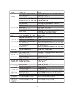
Symptom                  Possible Cause                                               Remedy

                                  Power off or loose electrical connection         Make sure main switch is ON. Check and tighten all connections.
                                  Incorrect thermostat setting                             Set thermostat correctly
No cooling                Defective contactor                                          Check for 24V at contactor coil.
                                  Open circuit breaker of blown fuses                Reset or replace
                                  Defective transformer                                      Check wiring - Replace it.
                                  Interconnecting low voltage wiring damage    Replace thermostat wiring
                                  Dirty filters                                                      Clean & replace
                                  Indoor air blockage                                          Check supply registers and return grills for blockage.
                                  Blocked outdoor coil                                       Clear away leaves and other debris
                                  Improperly sized unit                                       Recalculate load
Insufficient Cooling  Improper airflow                                              Check - should be 400CFM/Ton
                                  Incorrect refrigerant charge                              Charge correctly per instruction.
                                  Air, non-condensibles or moisture in system   Recover refrigerant, evacuate & recharge, add filter drier
                                  Incorrect voltage                                              At compressor terminals, voltage must be within
                                                                                                           10% of rating plate volts when unit is running.
Water on floor or in
furnace                      Blocked condensate drain and "P" trap           Remove blockage

Summary of Contents for HC18D1VAR

Page 1: ...24 K 10 to 13 SEER 1 5 to 5 Tons Models HC18 60A1VAR S HC18 60C1VAR HC18 60D1VAR Installation Operation Manual Central Air Conditioner The information contained in this booklet is subject to change without notice ...

Page 2: ...d service personnel for proper installation adjustment and operation of this unit Read these instructions thoroughly before attempting installation or operation Failure to follow these instructions may result in improper installation adjustment service or maintenance possibly resulting in fire electrical shock property damage personal injury or death This product is designed and manufactured to pe...

Page 3: ...ion can result in unsatisfactory operation or dangerous conditions Carefully read this manual and any instructions packaged with separate equipment required to make up the system prior to installation Give this manual to the owner and explain its provisions The owner should retain this manual for future reference 2 NOMENCLATURE FOR MODEL NUMBER H Brand symbol H Haier C System type C Air conditione...

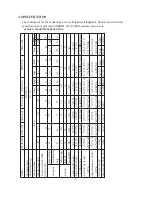
Page 4: ...ps 48 60 73 88 Full Load Amps 0 86 0 86 1 4 1 4 Fan Motor Rated HP 1 8 1 8 1 5 1 5 Nominal RPM 850 1000 1075 1075 Liquid Line OD In mm 3 8 9 52 3 8 9 52 3 8 9 52 3 8 9 52 Vapor Line OD In mm 5 8 15 88 5 8 15 88 3 4 19 05 3 4 19 05 R 22 Charge Oz g 49 47 1400 63 60 1800 88 34 2500 93 64 2650 Net Dimensions In mm 23 23 24 23 23 24 23 23 31 1 2 23 23 31 1 2 W D H 585 585 605 585 585 605 585 585 805 5...

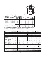
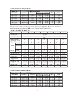
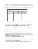
Page 5: ... 196 89 231 105 238 108 298 135 Approx Shipping Weight Lbs kg 141 64 143 65 152 69 222 101 257 117 264 120 321 146 183 75 5200 The dimensions for the condensing unit are illustrated in Figure 1 Physical and electrical specifications are provided in Table 3 for 12 SEER systems respectively 3 H W D Table 2 System Cooling Capacity Outdoor Unit With This Indoor Air handler Model Number HC18A1VAR HB240...

Page 6: ...0 705 770 770 805 770 770 805 770 770 905 770 770 805 770 770 905 Shipping Dimensions In mm 24 3 4 24 3 4 36 32 3 4 32 3 4 32 1 2 32 3 4 32 3 4 36 32 3 4 32 3 4 36 32 3 4 32 3 4 40 1 2 32 3 4 32 3 4 36 32 3 4 32 3 4 40 1 2 W D H 632 632 919 832 832 830 832 832 930 832 832 930 832 832 1030 832 832 930 832 832 1030 Net Weight Lbs kg 156 71 194 88 198 90 203 92 231 105 244 111 258 117 Approx Shipping...

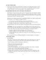
Page 7: ...trical power to the unit before servicing Disconnect power to both the indoor and outdoor units NOTE There may be more than one electrical disconnect switch Failure to shut off power can cause electrical shock resulting in personal injury or death Frequent washing of the cabinet fan blade and coil with fresh water Regular cleaning and waxing of the cabinet with good automobile polish A good liquid...

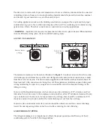
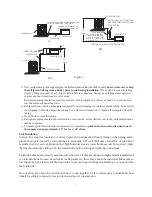
Page 8: ...ns are made from the service access area The most common application will find the unit best located about 10 from back wall with connection side facing the wall This application minimizes exposed tubing and wiring minimizing the space for youngsters to run around the unit with subsequent damage to the tubing or wiring In more confined application spaces such as corners provide a minimum of 10 cle...

Page 9: ...not kink or twist the tubing Refrigerant piping should not be installed in a cement slab as this limits access to the refrigerant should a leak be suspected To ensure good oil return to the compressor it is important to pitch the horizontal suction line toward the compressor approximately 1 2 for every 10 of line Line Insulation Suction line requires insulation in order to prevent condensation fro...

Page 10: ...n valves are closed to contain the charge within the unit Do not force the valve stem against the retaining ring If the valve stem is backed out past the retaining ring system pressure could force the valve stem out of the valve body and possibly cause personal injury CAUTION The piston is in the accessory bag Don t forget to take it out and put into the indoor liquid pipe orifice Instructions on ...

Page 11: ...which increases power consumption and reduces performance The presence of moisture in a system can render it inoperable in a very short time Proper evacuation assures a dry uncontaminated system Here is the recommended evacuation procedure 1 Connect vacuum pump to both liquid and suction valve service ports 2 Evacuate the interconnecting tubing and indoor coil to 500 microns or less for a minimum ...

Page 12: ...nd do not connect many devices to one AC outlet It could cause a fire or an electric shock due to defective contact defective insulation exceeding the permissible current etc Perform electrical work according to the installation manual and be sure to use an exclusive circuit If the capacity of the power circuit is insufficient or there is incomplete electrical work it could result in a fire or an ...

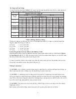
Page 13: ...re for disconnecting power service to the unit The condensing unit control wiring requires a 24 Volt minimum 25 VA service from the indoor transformer as shown on the wiring diagram 7 SYSTEM STARTUP 1 Turn thermostat to OFF turn on power supply at disconnect switch 2 Turn temperature setting as high as it will go 3 Turn fan switch to ON Indoor blower should run Be sure it is running in the right d...

Page 14: ...tions it can take up to 2 hours for this overload to reset Make sure overload has had time to reset before condemning the compressor 9 MISCELLANEOUS 9 1 Replacement Parts Contact your local distributor for a complete parts list 9 2 Troubleshooting Guide Refer to the troubleshooting guide Table 10 included in this manual 9 3 Wiring Diagram Refer to the appropriate wiring diagram included in this ma...

Page 15: ...llary tubes Replace coil assembly Low vapor cool Low evaporator airflow Increase blower speed or reduce restriction replace air filter compressor iced Operating below 65 F outdoors Add low ambient kit evaporator coil Moisture in the system Recover refrigerant evacuate recharge add filter drier High vapor Excessive load Recheck load calculation pressure Defective compressor Replace Fluctuating head...

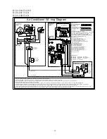
Page 16: ...H C BL BL YL YL Y 2 YL P3 P2 P1 6 RD R L1 GND L2 BK BK WH C S CC 4 RD YL 2 1 NC Optional Low High Pressur e Switches LPS HPS Compress or Protect 3 Min Time Delay BCAP RD LO RD L2 RD OR BK HI M IBM 3 GR PU L1 BK BK R S BR BR 208 COM BL R TRAN COM 230 7 BL 5 3 RD NO GR 8 6 4 OFM M BK PU PU BR 6 S R BR L1 L2 GND 60Hz 1PH 208 230V WH BK BCR 1 BK 2 RD BRK BK L2 RD RD FL L1 BK FL USE COPPER CONDUCTORS O...

Page 17: ...Made in P R C ...
Reviews: