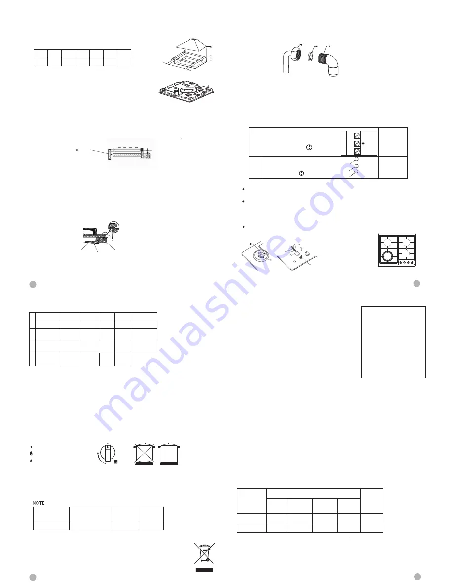
Detach the seals from their backing, that the transparent protection still adheres to the seal itself.
Turn over the hob and correctly position seal *E* (fig. 5) under the edge of the hob itself, so that the
outer part of the seal itself perfectly matches the outer edge of the hob. The ends of the strips must
fit together without overlapping. Evenly and securely fix the seal to the hob, pressing it firmly in place.
Unit:mm
A B C D E F G
557 477 65 62 150min 90min 750min
Fig 4
Fig 5
4
5
6
7
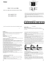
CONNECTION DIAGRAM
Caution! Voltage of heating elements 220-240V
Caution! In the event of any connection the safety
Wire must be connected to the
PE terminal.
Recommended
type of
connection
lead
For 220-240V earthed one -phase
connection, bridges connect L
terminals and terminals, safety
wire to
N
L
PE
N
L
N
a
Worktop
Fixing bracket
Screw
edge of the hob. It is important to fix this gasket evenly, without gaps or overlapping to prevent
not to damage the ignition plugs and the thermocouples.
on the cabinet.
Secure the hob to the underside of the worktop using the fixings provided.
Screw one end of the bracket into the pre-drilled holes in the underside of the hob.
The other end of the bracket should be located underneath the worktop to secure
liquids from seeping underneath the hob.
The panel underneath the hob must be easily removable to allow for any servicing requirements
Inserting and fixing the hob
Before inserting the hob into the work surface, place the adhesive seal (a) around the underside
1) Remove the pan stands and the burner caps then turn the hob upside down, taking care
2) Place the gasket around the bottom edge of the hob as shown in the illustration overleaf (left).
3) Place the hob in the installation opening and push it down so that the hob is resting firmly
4) Secure the hob in position using the fixing brackets supplied.
the hob in position.
GAS CONNECTION
The appliance's gas inlet fitting is a 1/2" male threaded conic gas type in accordance with the
ISO 7-1
standards. Make the connection using rigid pipe.
ELECTRICAL CONNECTION
This appliance must be connected by a competent person, using fixed wiring via a double pole
switched fused spur outlet with a fuse rating of 3amps, and with a contact separation of at least
We recommend that the appliance is connected by a qualified electrician who will comply with
When making the gas connection, it is important to place the gasket (A)
in between the inlet pipe (C) and the elbow (B), to
ensure a gas tight seal.
3mm in all poles.
I.E.E regulations.
Ventilation slot
> 30mm
for overcoming this problem is to fix a wooden panel within the cabinet at a distance of 15mm below
the underside of the hob (see fig 1). This panel must have adequate ventilation to the rear.
When fitting a gas hob above a drawer or standard housing unit, suitable precautions must be taken
to prevent contact.
with the casing of the hob, which becomes very hot during operation. The recommended method
Installation options
Option:
The wires in the mains lead are coloured in accordance with the following code: Green & Yellow = Earth,
Blue = Neutral, Brown = Live.
Replace the injectors with the corresponding injector from the table on page below.(see fig. 6).
First remove the burner caps and rings and with a socket spanner "B", unscrew Injector "A" (see fig. 6).
The adjustment of the reduced rate position is as follows (fig. 7):
Light the burner and turn the knob to reduced rate position.
Remove the knob "M" which is simply inserted onto, tap stem.I
Insert a small screwdriver "D" into the top shaft "C" and turn the bypass screw left or right until
flame of the burner is conveniently regulated to the low position.
Make sure that when turning quickly from "Full on" position to reduced rate position that the
C
D
Fig 6 Fig 7
INJECTOR REPLACEMENT TABLE
burner does not extinguish.
A
B
D
C
E
E
G
F
SELECT THE RIGHT BURNER
Use an appropriately sized pan and with flat bottom for each burner (see the table below and fig. 9).
6. USER INSTRUCTIONS
1.To light the hotplate push In the appropriate control knob and turn anti-clockwise to the large
2.Keep the knob depressed until the burner lights.
3.Turn the tap to the required setting.
4.In the event of the burner flames being accidentally extinguished, turn off the burner control and
don’t attempt to reignite the burner for at least 1 min.
flame symbol (fig. 8).
NOTE: Matches can be used to light the burners in the event of a power failure.
N
NO
OTTE
E: Please not use cooking vessels that overlap the boundaries of the hob
Keep the control knob pressed in for 15 seconds ensuring the burner stays lit when released.
WARNING
When the contents of the pan start to boil, turn the knob down to reduced rate position. Always
Fig 8 Fig 9
Closed position
Full on position
Reduced rate position
If the burner fails to stay lit wait for 1 minute before relighting.
put a lid on the pan.
Burners
Semirapid
Auxilary
φ
pans in cm
24-26
16-18
10-14
Triple Flame
Correct Disposal of this product:
This marking indicates that this product should not be disposed with other household
wastes throughout the EU. To prevent possible harm to the environment or human
health from uncontrolled the sustainable reuse of material resources. waste disposal,
recycle it responsibly to promote To return your used device, please use the return
and collection systems or contact the retailer where the product was purchased.
They can take this product for environmental safe recycling.
Check the guide below if there Is a problem with your hob.
UNEVEN OR YELLOW FLAME RA THER THAN BLUE.
Switch off and check the following points:
1.Are the burners fitted correctly?
2.Are the holes in the burner clear?
3.Check that no dust has fallen into the flame turning it yellow
BURNER FAILING TO IGNITE?
Check that the power is turned on or that the fuse has not blown.
Make sure that the ignitor isn't coated with food spillage.
SPARK BUT NO GAS?
Make sure the gas is turned on.
Check that the burner holes are not blocked.
SMELL GAS?
Check to see if any gas tap has been left on..
If they are off, switch off gas at mains and call a service agent.
DO NOT search with a naked flame, strike any matches or press ignitor.
STILL NOT WORKING?
Call the service agent.
7. FAULT FINDING GUIDE
ATTENTION!!!!!
This appliance must be installed in
compliance with the current
provisions in force and only used in
rooms equipped with adequate
ventilation.
Consult the instruction manual before
proceeding with installation or use of
the appliance.
About ErP
A) Measurement and calculation methods
● The gas hob was CE approval according to the Gas Appliance Directives 2009/142/EC.
● The energy efficiency of this gas hob was tested and measured according to EN 30-2-1-1998+A1-2003+A2-2005.
● The semi-rapid burner and rapid burner were tested separately; the auxiliary burner is not required for test because its
nominal heat input is less than 1.16kW.
● The energy efficiency of the gas burners and the hob were calculated according to COMMISSION REGULATION (EU) No.
66/2014.
B) Rational use of the energy and the appliance
● The gas hob is designed for domestic use only, please do not use for commercial.
● The gas hob is designed for use with gas (LPG and Natural gas), the combustion products contain carbon monoxide and
carbon dioxide, the exhaust of combustion products is affecting our environment when reach a certain amount of CO and
CO2.
● To ensure the rational use of energy, please install the gas hob according to the specifications in clause 5, and please make
sure you are using the correct diameter of pan for each burner.
● To ensure the safety use, please read this instruction manual before use; please follow the installation, operation and
maintenance guideline.
● To ensure the optimal life expectancy of the gas hob, please follow the operation and maintenance guideline strictly; please
do not modify the appliance.
● Please contact your local after-sale service for repairing and exchanging of the components (such as gas valve, control
knob) if necessary.
● The materials of the gas hob is metal, please dispose the gas hob recycling when the gas hob comes to the end-of-life.
● The packaging materials of this appliances is recyclable, please makegooduseof waste materials.
Model
EE
gas burner
EE
gas hob
Small
(Auxiliary)
Medium
(Semi-rapid)
Big (Rapid)
Triple
N/A
N/A
N/A
N/A
56.0%
56.0%
54.0%
55.0%
56.5%
56.0%
E
E
4
1
2
2
13.7 MJ/H
3.6 MJ/H
6.3 MJ/H
2016.02.01-02
HCG604WFCX2
HCG604WFCG1
HCG604WFCX2
HCG604WFCG1
BURNERS
NORMAL
PRESSURE
NORMAL
RATE
INJECTOR
DIAMETER
NOMINAL HEAT
INPUT (MJ/h)
DESCRIPTION
GAS
mbar
1/100 mm
MIN.
1
2
3
SEMIRAPID
BUTANE
PROPANE
NATURAL
28-30
37
11.3
68
68
111
AUXILIARY
BUTANE
PROPANE
NATURAL
28-30
37
11.3
52
52
87
2.88
2.88
2.88
2.16
2.16
2.16
3.6
6.3
9.36
9.36
9.36
13.7
103
103
162
TRIPLE
FLAME
BUTANE
PROPANE
NATURAL
28-30
37
11.3
13.7
13.7
3.6
3.6
MJ/h
6.3
6.3


