


ENGLISH
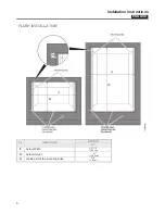
Installation Instructions
8
ELECTRICAL CONNECTIONS
Be sure your appliance is properly installed and grounded
by a qualified technician. Ask your dealer to recommend a
qualified technician or an authorized repair service.
This appliance is manufactured with a green GROUND wire
connected to the oven chassis. After making sure that the
power has been turned off, connect the flexible conduit from
the oven to the junction box using a U.L. listed conduit
connector. Figures A and B and the instructions provided
below present the most common way of connecting the ovens.
Your local codes and ordinances, of course, take precedence
over these instructions. Complete electrical connections
according to local codes and ordinances
“WARNING” Risk of Electric Shock, frame grounded to
neutral of appliance through a link
.
Grounding through the neutral conductor is prohibited for new
branch-circuit installations (1996 NEC); mobile homes; and
recreational vehicles, or in an area where local codes prohibit
grounding through the neutral conductor. For installations
where grounding through the neutral conductor is prohibited:
Disconnect the ground from the neutral at free end of
conduit;
Use grounding terminal or lead to ground unit; and
Connect neutral terminal or lead to branch circuit neutral in
usual manner.
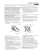
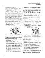
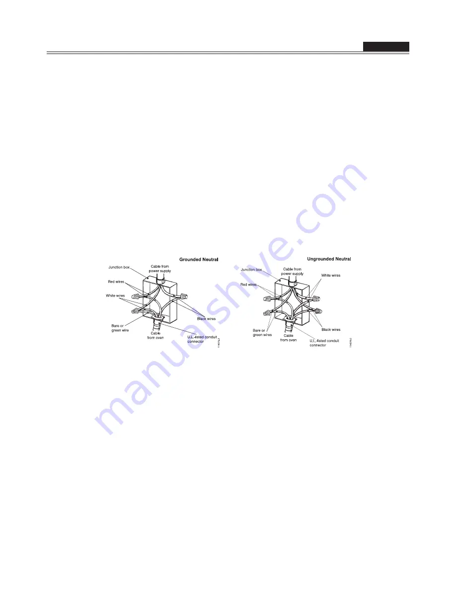
3-WIRE BRANCH CIRCUIT
(for US only)
Refer to Figure A, where local codes allow the connection of
GROUND wire from the oven to the branch circuit NEUTRAL
wire (gray or white colored wire):
If local codes permit, connect the green GROUND wire
from the oven and the white wire from the oven to the
branch circuit NEUTRAL wire (gray or white colored wire).
Connect the red and black leads from the oven to the
corresponding leads in the junction box.
4-WIRE BRANCH CIRCUIT
(for US and CANADA)
Refer to Figure B:
Disconnect ground from neutral at free end of conduit.
Connect the green GROUND wire from the oven to the
GROUND wire in the junction box (bare or green colored
wire).
Connect the red and black leads from the oven to the
corresponding leads in the junction box.
Connect the white wire from the oven to the NEUTRAL
(gray or white) wire in the junction box.
Figure A
Figure B
FINAL CHECKLIST
To prevent improper connections leading to damage of
electrical components and so voiding the warranty, the
following steps must be performed:
1. Check the electrical requirements and make sure you have
the correct electrical supply and that the oven is properly
grounded.
2. Turn on the power supply to the oven.
3. Check power at the junction box wires using a voltmeter
having a range of 0-250 VAC.
If you have installed the oven for use on 240 Volt supply,
you should find that the voltage reading between the black
and red wires (Line to Line) should be 220 to 240 Volts.
If you have modified the oven(s) for use on 208 Volt, the
voltage reading between the black and red wires should be
190 to 208 Volts.
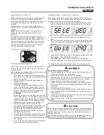
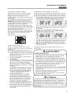
4. Set the clock by following these steps:
Press [TIME] key twice until the display shows “SET TIME”.
Immediately press [INC] or DEC] keys to set hours.
Press [TIME] key again to change minutes.
Immediately press [INC] or DEC] keys to set minutes, hold
to change by ten (10) minutes step.
Press [TIME] key or wait for a few seconds.
Clock is now set.
5. Test the bake mode by following this step:
Move cooking mode knob to “BAKE” position.
Cooling fan, oven lights, preheat led will turn on.
A beep is sounded when the oven reaches the preset
350 °F (175 °C) and the preheat light turn off.
Move the knob back to “OFF” position to stop cooking.
6. To check the other oven functions refer to the “Using the
Oven Controls” section of the USE AND CARE MANUAL.
7. If the oven is working properly, turn off the power supply to
the oven.
8. Place the cover on the junction box and make sure the
cover is securely fastened and turn on the power to the
oven.
Leave these INSTALLATION instructions as well as the
USE AND CARE MANUAL with the owner.
Summary of Contents for HCW3485AES
Page 2: ......
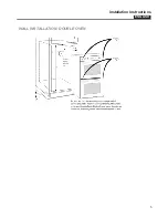
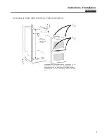
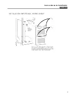
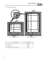
Page 5: ...ENGLISH Installation Instructions 5 WALL INSTALLATION DOUBLE OVEN...
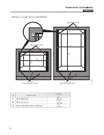
Page 11: ...FRAN AIS Instructions d Installation 11 INSTALLATION DES PAROIS FOUR DOUBLE...
Page 17: ...ESPA OL Instrucciones de Installaci n 17 INSTALACI N EMPOTRADA HORNO DOBLE...
Page 21: ...Notes...
Page 22: ...Notes...
Page 23: ......


