5
5
4
4
3
3
2
2
1
1
D
D
C
C
B
B
A
A
Page 15 - Power and Gnd 3
Page 16 - Power and Gnd 4
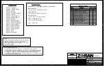
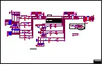
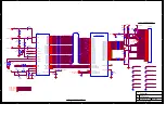
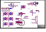
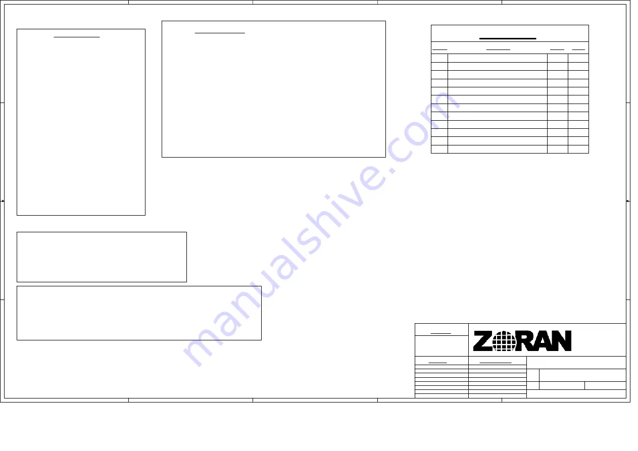
Sheet Index
Page 01 - Title Sheet
Page 02 - DDR SDRAM I/F
Page 03 - SIO I/F
Page 04 - HDMI I/F
Page 05 - Tuner / Demodulator
Page 06 - Audio In
Page 08 - Analog Video I/F
Page 09 - Audio I/F
Page 11 - GPIO / Test Block
Page 10 - Digital Video I/F
Page 12 - MISC & Connectors
Page 13 - Power and Gnd 1
Page 14 - Power and Gnd 2
Page 07 - Video Decoder I/F
Page 17 - LVDS
Note: * - Default setting.
A)
Stuffing Options
B)
R3,R4,R9,R10 - IN, R5,R6,R7,R8 -OUT Boot-up from SPI FLASH *
C)
R203, R205 - OUT *
R203, R205 - IN - LCD Backlight levels setup
D)
E)
SW1 - IN - Development only *
SW1 - OUT - Production Version
R201, R202 - OUT *
R203 or R205 - IN - Backlight inverter setup
R160, R164 - OUT *
R160 or R164 - IN - LVDS receiver setup
Page 18 - MCU
Page 19 - GPIO Table
B1
Peripheral parts of U27 revised.
B2
B2
LVDS OUTsignals rearranged
SD Video IN rearranged (p7)
GPIOs 4, 5, 30 and 31 reassigned
U16 package changed
R236 connected to +5V
Pin U6.27 connected to +2.5V
B1
B1
B1
B1
B1
B1
C269, C270 are changed
L8 & R96 are changed
Notes: (unless otherwise stated)
1.
2.
3.
4.
All resistors are listed in ohms and are 5%, 1/16W, Metal Film (0603 form factor)
All capacitors are listed in microfarads, and are 10%, 25V, ceramic, X7R (0603 form factor)
All inductors are listed in microhenries, and are 5%, 100ma, non-wound (0805 form factor)
"Signal Ports" and "Off Page Connectors" are Global, and transition between sheets.
5. Signal "Names" without "Signal Ports" or "Off Page Connectors" are Local, and only connect
like named signals on the same sheet.
760
<Fab #>
<Assy #>
<Tree #>
1390 Kifer Road
Sunnyvale Ca 94086
(408) 523-6500
http://www.zoran.com
Project :
Reference:
Release Approvals
Applications
Marketing
Operations
Product Mgr.
Fab.
Assy.
Schem
Tree
N/A
Notice -
This document contains proprietary and confidential information of
ZORAN Inc., Distribution, transmission, or duplication
of this material in written or any other form without the express
written consent of ZORAN Inc., is prohibited.
Copyright 2006 ZORAN Inc.
B2
Sabercat
B
1
17
Thursday, May 10, 2007
760_B2.DSN
Title
Size
Document
Rev
Date:
Sheet
of
Drawn by: O. Marinovsky
Revision History
Revision
Description
P. Mgr.
Date
A
Initial Release
Summary of Contents for HL32S-A
Page 1: ...HL32S A...
Page 5: ...Safety Precautions...
Page 7: ...b Printed Circuit IC Board 1 head on board...
Page 8: ...2 rear board...
Page 9: ...Key IC Description Trouble Shooting Guide 1 Key IC Description 1 ZORAN39760...
Page 10: ...2 HYB25DC256163CE 4...
Page 11: ...3 AD9883...
Page 12: ...4 M25P32...
Page 13: ...2 Trouble Shooting Guide...
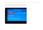
Page 16: ...2 SW SW This is the current software version...
Page 17: ...2 Aging Mode This is for factory run in testing...
Page 18: ...3 RF Upgrade is for debugging and do not change anything commonly...
Page 19: ...4 Service Menu is for debugging and do not change anything commonly...
Page 21: ...2 Others...
Page 22: ......
Page 23: ......
Page 24: ...Circuit Diagram 1 BCM signal flowing chart 2 Circuit Diagram...
Page 43: ...Connection Sketch Interpretat...
Page 44: ......


