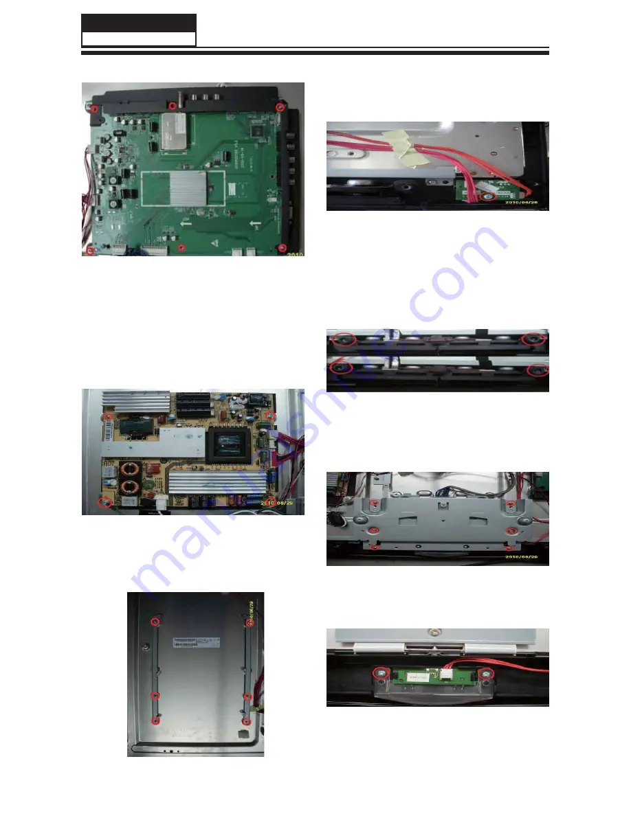
Then put the terminal bracket to the side.
Disconnected the coupler CNE1 CNE2 CN14
CN11 CN17 CON2.
Remove the Mainboard.
3-5. Remove the Power Supply
Modules
Remove the four screws indicated by the
red circles in below picture.
Then remove the power supply module.
3-6. Remove the Terminal Bracket
3-7. Remove the Remote Control
Board
Remove the one screw indicated by red
circles in below picture.
Disconnected the coupler CNE3 and CNE2
Remove the remote control board.
3-8. Remove the Speaker
Remove the four rubber bands indicated by
the red circles in below picture.
Take out the speakers.
3-9. Remove the Stand Backstop
Remove the six screws indicated by the red
circles in below picture.
Take out the stand backstop.
3-10. Remove the Indicator Light
Remove the two screws indicated by red
circles in below picture.
Disconnected the coupler CN2,
Remove the indicator light.
Remove the six screws indicated by the red
circles in below picture.
Service Manual
Model No.: HL37XLE2
12
Summary of Contents for HL37XLE2
Page 10: ...Service Manual Model No HL37XLE2 9 2 2 External pictures four faces Front Side Left Side ...
Page 11: ...Service Manual Model No HL37XLE2 10 Right Side Back Side ...
Page 49: ...8 2 4 Picture Mode Service Manual Model No HL37XLE2 48 ...
Page 50: ...8 2 5 Audio Mode Service Manual Model No HL37XLE2 49 ...


