4-2-1. Function Description:
Main Board
Process signal which incept from exterior equipment then translate into signal that panel can display.
4-2-2. Connector de
fi
nition
Main board connector
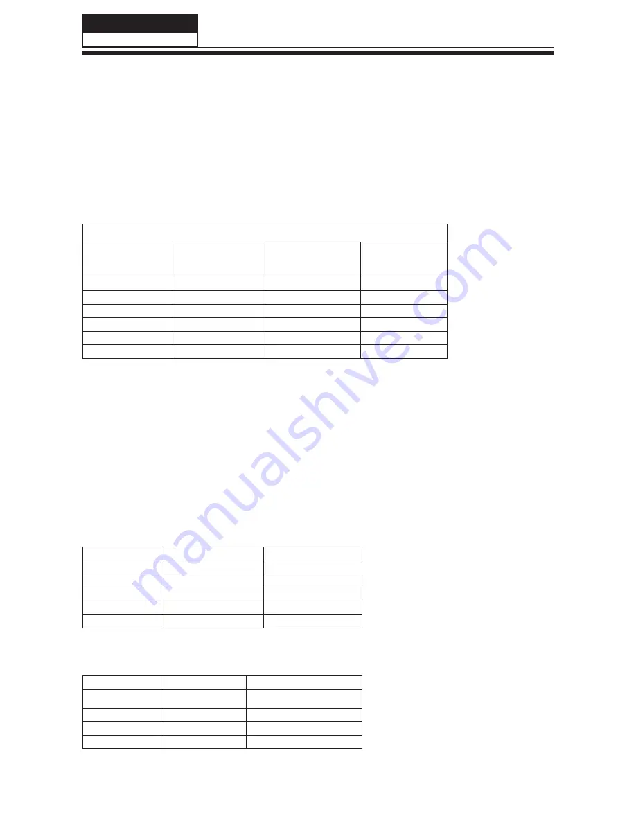
Power connectors (CN17)
CN17
Pin number
Signal name
Pin number
Signal name
1
+12V
7
5V_STB
2
+12V
8
BRT_CNTL_OUT
3
GND
9
GND
4
+12V
10
SW_POWER
5
GND
11
NC
6
GND
12
BL_ON/OFF
Notes:
CN17-Pin 12: Backlight on/off:
The system can turn on or turn off the backlight of TFT LCD Panel through the power supply
unit path.
CN17-Pin 10: System power on / standby
System board will use this pin to control system power.
CN17-Pin 8: Control the luminance of backlight
The system can generate the PWM signal to control the strength of TFT LCD Panel’s
backlight through this connector
Pin number
Signal name
Description
1
5VS
5V
2
IR-IN
IR
3
LEDR
LAMP RED
4
LEDB
LAMP BLUE
5
GND
GND
Remote connector (CNE1)
Pin number
Signal name
Description
1
GND
GND
2
KEY0
KEY0
3
KEY1
KEY1
4
3.3VS
3.3V
Keypad connector (CNE2)
CN17
Pin number
Signal name
Pin number
Signal name
1
+12V
7
5V_STB
2
+12V
8
BRT_CNTL_OUT
3
GND
9
GND
4
+12V
10
SW_POWER
5
GND
11
NC
6
GND
12
BL_ON/OFF
Service Manual
Model No.: HL37XLE2
14
Summary of Contents for HL37XLE2
Page 10: ...Service Manual Model No HL37XLE2 9 2 2 External pictures four faces Front Side Left Side ...
Page 11: ...Service Manual Model No HL37XLE2 10 Right Side Back Side ...
Page 49: ...8 2 4 Picture Mode Service Manual Model No HL37XLE2 48 ...
Page 50: ...8 2 5 Audio Mode Service Manual Model No HL37XLE2 49 ...


