Introduction
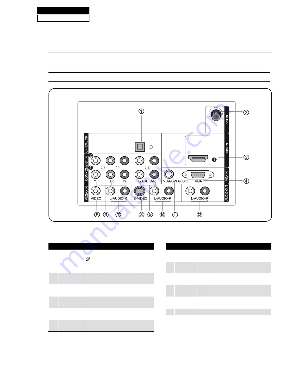
1
Digital Audio
Output
Connect various types of digital audio equipment.
Note
In standby mode, these ports will not
R
work.
2
Antenna
Input
Connect cable or antenna signals to the TV,
either directly or through your cable box.
3
HDMI In
Connect a HDMI device to receive digital audio
and uncompressed digital video.
4
VGA Video In
Connect a video cable from a computer to this
jack.
5
VIDEO In
Connect the video signal from a video device to
this jack.
6
Component
Video In
Connect a component video device to these
jacks.
7
AUDIO In
Connect the audio L/R cables from the video signal
source to these jacks.
8
S-VIDEO In
Connect the S-Video cable from an external signal
source to this jacks.
9
COMPONENT
AUDIO In
Connect the audio L/R cables from the component
video signal source to these jacks.
0
AUDIO In
Connect the audio L/R cables from the S-Video
signal source to these jacks.
A
VGA Audio
In
Connect the audio L/R cables from a computer to
this jack.
B
AUDIO Out
Connect the audio L/R cables to your audio equipment.
Connection Options
Back panel connections
Service Manual
Model No.: HL40XP1
26
6-2. Back Panel Controls
Summary of Contents for HL40XP1
Page 10: ...Service Manual Model No HL40XP1 9 2 2 External pictures four faces Front Side Left Side ...
Page 11: ...Service Manual Model No HL40XP1 10 Right Side Back Side ...
Page 18: ...4 4 1 Function Description Display the signal Service Manual Model No HL40XP1 17 ...
Page 19: ...Service Manual Model No HL40XP1 18 ...
Page 49: ...8 2 2 Auto Color Service Manual Model No HL40XP1 48 ...
Page 50: ...8 2 3 Whinte Balance Color Temp 8 2 4 Picture Mode Service Manual Model No HL40XP1 49 ...
Page 52: ...8 2 7 Aging Mode 8 2 8 Power On Mode Service Manual Model No HL40XP1 51 ...
Page 53: ...8 2 9 Camma Table 8 2 10 Reste to default Service Manual Model No HL40XP1 52 ...
Page 54: ...8 2 11 Reset all setting to default Service Manual Model No HL40XP1 53 ...
Page 56: ...9 2 Power Supply Board Failure Check Service Manual Model No HL40XP1 55 ...


