5
5
4
4
3
3
2
2
1
1
D
D
C
C
B
B
A
A
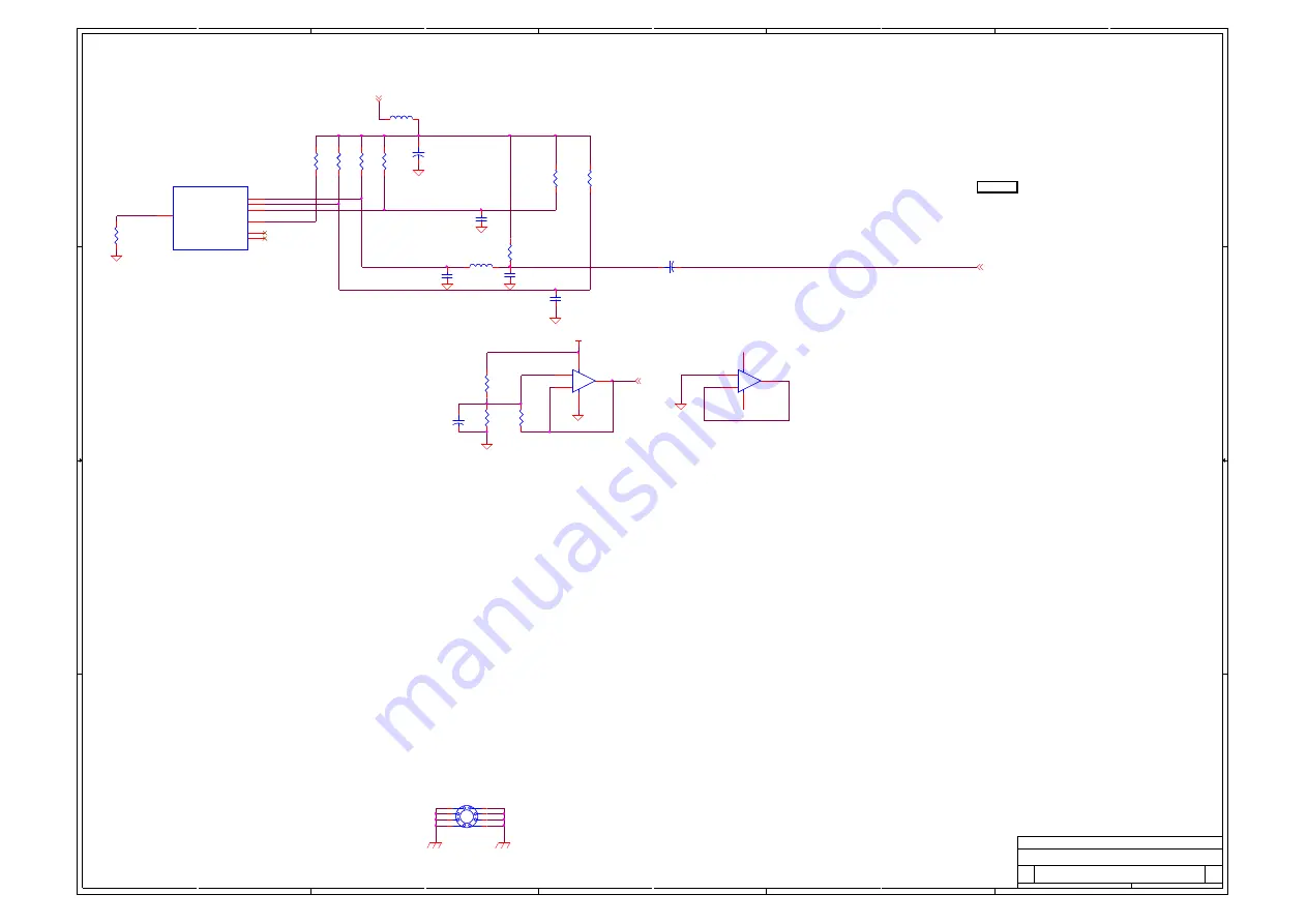
MAIN3560_OUT_Y
VDAC_RBIAS
VDAC3_HSYNC
VDAC1_Y
VDAC2_PB
VDAC0_PR
A
A
A5.0V
A
A
A
A
A
A
A
VDAC_AVDD3P3
(14)
AUD-REF
(9)
MAIN3560_OUT_Y
(5)
Title
Size
Document Number
Rev
Date:
Sheet
of
<Doc>
?
<Title>
C
7
18
Tuesday, November 07, 2006
Title
Size
Document Number
Rev
Date:
Sheet
of
<Doc>
?
<Title>
C
7
18
Tuesday, November 07, 2006
Title
Size
Document Number
Rev
Date:
Sheet
of
<Doc>
?
<Title>
C
7
18
Tuesday, November 07, 2006
VDAC_AVDD33 needs to be very clean. If you use
switching supplies, consider using a small linear
regulator for this supply. (250 mA worst case)
Place 75 ohm
terminations <1"
from BCM3560
Route VDAC_AVDD33 as a wide trace or fill area on
the top layer of the PCB all the way to the connector
MAIN_OUT
R289
NC
R289
NC
R250
560
R250
560
R284
NC
R284
NC
+
C423
33uF
+
C423
33uF
5
6
7
8
4
+
-
V+
V-
U35B
LM358M
SO8
+
-
V+
V-
U35B
LM358M
SO8
GPIO_40/HSYNC
B16
GPIO_41/VSYNC
A16
VDAC0_0
A14
VDAC0_1
C14
VDAC0_2
D14
VDAC0_3
B14
VDAC_RBIAS
B15
Analog Video
Outputs
U22O
BCM3551KPB5G
BGA676_35X35
Analog Video
Outputs
U22O
BCM3551KPB5G
BGA676_35X35
R592
NC
R592
NC
C418
220pF
C418
220pF
1
2
4
3
5
6
7
8
MH3
4-40X3/4in-SCREW (DNI)
MH3
4-40X3/4in-SCREW (DNI)
3
2
1
8
4
+
-
V+
V-
U35A
LM358M
SO8
+
-
V+
V-
U35A
LM358M
SO8
R298
75
R298
75
L41
2.2uH
L41
2.2uH
+
C173
100uF
10V
+
C173
100uF
10V
R573
2.2K
R573
2.2K
C460
33pF
C460
33pF
C415
220pF
C415
220pF
R583
2.2K
R583
2.2K
L118
MPZ2012S221A
L118
MPZ2012S221A
R301
NC
R301
NC
+
C139
47uF
10V
+
C139
47uF
10V
R283
0-NC
R283
0-NC
C461
33pF
C461
33pF
R304
NC
R304
NC
R290
75
R290
75
Summary of Contents for HL42B
Page 1: ...HL42B ...
Page 5: ...Safety Precautions ...
Page 6: ... ...
Page 7: ... Images of Module and Circuit Boards a Signal flow chart ...
Page 8: ... b Printed Circuit IC Board 1 head on board ...
Page 9: ... 2 rear board ...
Page 10: ... Key IC Description Trouble Shooting Guide 1 Key IC Description 1 BCM3551 ...
Page 11: ... 2 MSP3460 ...
Page 12: ... 3 AD9880 ...
Page 13: ... 2 Trouble Shooting Guide ...
Page 14: ... Signal Flowing Chart ...
Page 19: ... 2 Aging Mode This is for factory run in testing ...
Page 20: ... 3 Shop End is for debuging and do not change anything commonly ...
Page 21: ... 4 Service Mode is for debugging and do not change anything commonly ...
Page 22: ... 5 Design Mode includes 4 items Video Setting Audio Setting Screen Setting Others ...
Page 27: ... 2 Others ...
Page 28: ... ...
Page 29: ... ...
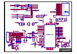
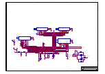
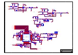
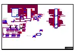
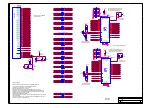
Page 30: ... Circuit Diagram 1 BCM signal flowing chart 2 Circuit Diagram ...

