19
Service Manual
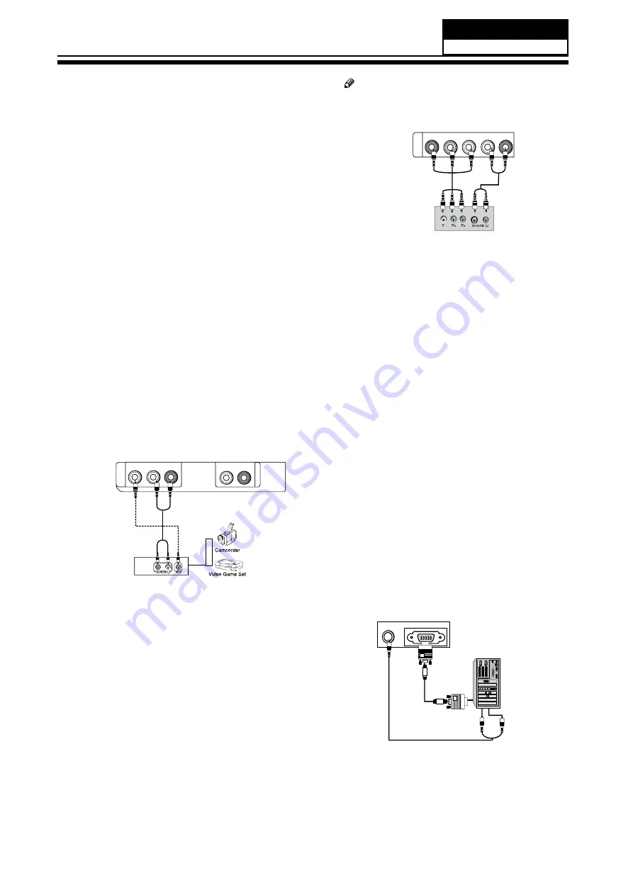
Connection Option 1
Set VCR output switch to channel 3 or 4 and then tune
the TV to the same channel number.
Connection Option 2
Connect the audio and video cables from the VCR’s
A
output jacks to the TV input jacks, as shown in the
figure. When connecting the TV to VCR, match the
jack colors (Video = yellow, Audio Left = white, and
Audio Right = red). If you connect a S-VIDEO output
from VCR to the S-VIDEO input, the picture quality is
improved; compared to connecting a regular VCR to
the Video input.
Insert a video tape into the VCR and press
B
PLAY
on
the VCR. (Refer to the VCR owner’s manual.)
Select the input source with using the
C
INPUT
button
on the remote control, and then press
/
button
to select the source, press
ENTER
button to confirm.
A/V Source Setup
Connect the audio and video cables from the
A
external equipment’s output jacks to the TV input
jacks, as shown in the figure.
When connecting the TV to external equipment,
B
white, and Audio Right = red).
VIDEO
A
V
IN
AUDIO OUT
L R
L -AUDIO- R
How to use
Select the input source with using the
A
INPUT
on the remote control.
Operate the corresponding external equipment.
B
Refer to external equipment operating guide.
Component Setup
How to connect
Connect the DVD video outputs (COMPONENT) to
A
the Y Pb Pr jacks on the TV and connect the DVD
audio outputs to the YPbPr Audio IN jacks on the TV,
as shown in the figure.
If your DVD only has an S-VIDEO output jack, connect
B
this to the S-VIDEO input on the TV, as shown in the
figure.
Note
If your DVD player does not have
R
component video output, use S-Video.
COMPONENT
IN
Y Pb Pr
L -AUDIO- R
How to use
Turn on the DVD player, insert a DVD disc.
A
Use
B
INPUT
button on the remote control to select
proper input.
Connecting a computer
How to connect
To get the best picture quality, adjust the VGA
A
graphics card to 1024
s
768.
Use the TV’s VGA or DVI (Digital Visual Interface)
B
Audio IN port for audio connections, depending on
your computer connector.
If the graphic card on the computer does not
q
output analog and digital RGB simultaneously,
connect only one of either VGA IN or HDMI IN to
display the VGA on the TV.
If the graphic card on the computer does output
q
analog and digital RGB simultaneously, set the TV
to either VGA or HDMI; (the other mode is set to
Plug and Play automatically by the TV.)
Then, make the corresponding audio connection.
C
If using a sound card, adjust the VGA sound as
required.
PC/DVI AUDIO IN
PC IN
9*$,1
Model No.: HLC24XSLW2a
Summary of Contents for HLC24XSL2
Page 10: ...Service Manual 9 2 2 External pictures four faces Front Side Left Side Model No HLC24XSLW2a ...
Page 11: ...Service Manual Model No HLC24XSLW2a 10 Right Side Back Side ...
Page 18: ...Service Manual 17 Panle LVDS Connector CNC4 Model No HLC24XSLW2a ...
Page 28: ...Service Manual 7 3 Wiring Connection Diagram 27 Model No HLC24XSLW2a ...
Page 29: ...28 Service Manual Model No HLC24XSLW2a ...
Page 30: ...Service Manual 29 Model No HLC24XSLW2a ...
Page 31: ...30 Service Manual Model No HLC24XSLW2a ...
Page 32: ...Service Manual 31 Model No HLC24XSLW2a ...
Page 33: ...32 Service Manual Model No HLC24XSLW2a ...


