14
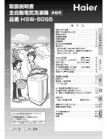
WIRING DIAGRAM
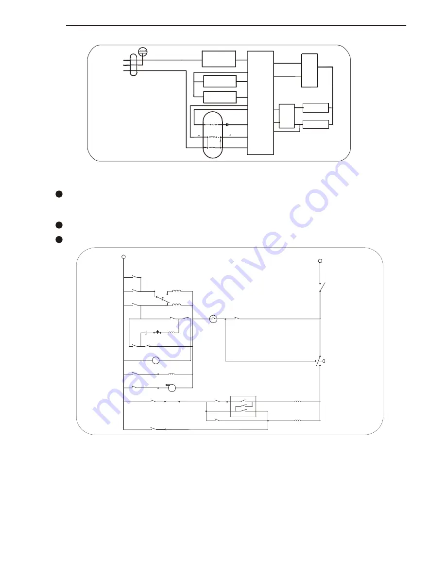
Actual Circuit Diagram(Please reference the next page)
There is overload protector installed in the motor. In case that the motor is overload or meets
breakdown in working, the protector will act and stop the motor. When the breakdown is
removed, the motor will resume normal working.
Figure 5-2
The capacitor should not be assembled if the motor voltage is 220-240V.
Figure 6
BLK
Interm
Agit
ORG
6-PM Run Coil
Run
Low Motor
High
Motor
Start
Motor
Blue
4-PM Start Coil
YEL
Wash
(CCW)
Spin
(CW)
Start Coil
(AUX)
Start
Run
RED
Motor
Spin
(CW)
Wash
(CCW)
Timer Motor
Actuator
BLUE/WHT Actuator
YEL/WHT
Pump
Pump
Fill
Intermittent
Spray
Wash
Wash Temp Switch
Brown
Grey
Rinse
1
2
3
Pink
YEL/RED
Hot Valve
Cold Valve
RED/BLK
Full
ORG
Empty
WHT
WHT
WHT
Lid Switch
L1
L2
Thermal
Protector
Bypass
BLK/WHT
Door switch
Drain pump
Drain motor
Timer
Com
Full
Empty
Water
level
Switch
Hot valve
Cold valve
Motor
C
M4
M2
M3
M5
M1
M6
L
H
AUX