44
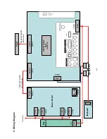
9. Wiring Diagram
095G
801
832
D90
1
095G
-82
513
X930
Wire Ha
rne
ss
IR Board
5 Pin
CN201
Pow
er Board
CN901
Ke
y
Board
Panel
CN902
CN
01
2 Pin
CN803
S
p
eaker R/L
T
o
Panel
32 Pin
ZR39
787
HG
CF
U40
1
Scaler IC
L
V
DS Cable
CN408
12 Pin
CN701
CN606
13 Pin
4 Pin
4 Pin
CN804
2 Pin
10 Pin
CN401
2 Pin
CN805
2 Pin
CN802
Summary of Contents for L19
Page 17: ...17 4 Mechanical Instructions Step1 Remove the STAND ASS Y Step2 Remove the REAR COVER ...
Page 19: ...19 Step 5 Separate the MAIN FRAME and PANEL Step 6 Remove the KEY BOARD IR BOARD and SPEAKERS ...
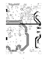
Page 27: ...27 6 PCB Layout 6 1 Main Board 715G3759M02000005K ...
Page 28: ...28 ...
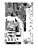
Page 29: ...29 6 2 Power Board 715G3754P01W30003H ...
Page 30: ...30 ...
Page 31: ...31 ...
Page 32: ...32 6 3 Key Board 715G3303 2 6 4 IR Board 715G3963R01000004S ...

