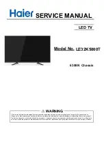


SERVICE MANUAL
LED TV
Chassis
6308N
This service information is designed for experienced repair technicians only and is not designed for use by the general public.
It does not contain warnings or cautions to advise non-technical individuals of potential dangers in attempting to service a product.
Products powered by electricity should be serviced or repaired only by experienced professional technicians. Any attempt to
service or repair the product or products dealt with in this service information by anyone else could result in serious injury or death.
WARNING
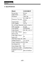
LE32K5000T
Model No.
Summary of Contents for LE32K5000T
Page 11: ...3 3 LED Panel 10 Service Manual Model No ST3151A05 5 ...
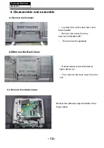
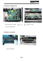
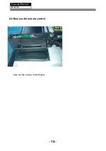
Page 15: ...4 6 Remove the remote control take out the remote controlboard Service Manual Model No 14 ...
Page 27: ......
Page 28: ......
Page 31: ......
Page 55: ...Service Manual Model No 9 Trouble shooting 9 1 Simple check 54 ...
Page 56: ...Service Manual Model No 9 2 Main board failure check 55 ...
Page 62: ... Power Module not work 61 ...