background image

SERVICE MANUAL

LED TV

Chassis

MSD

34631

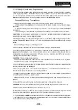
This service information is designed for experienced repair technicians only and is not designed for use by the general public. 
It does not contain warnings or cautions to advise non-technical individuals of potential dangers in attempting to service a product.
Products powered by electricity should be serviced or repaired only by experienced professional technicians. Any attempt to 
service or repair the product or products dealt with in this service information by anyone else could result in serious injury or death.

WARNING

LE3

9

B8

5

5

0

T

Model No.

Summary of Contents for LE39B8550T

Page 1: ...gs or cautions to advise non technical individuals of potential dangers in attempting to service a product Products powered by electricity should be serviced or repaired only by experienced professional technicians Any attempt to service or repair the product or products dealt with in this service information by anyone else could result in serious injury or death WARNING LE39B8550T Model No ...

Page 2: ...and Assemble 4 1 Remove the Stand Base 6 7 7 7 11 11 4 2 Remove the Back Cover 11 4 3 Remove the Adhesive Tape 11 4 4 Remove the Main Board 12 4 5 Remove the Speaker 12 4 6 Remove the Remote Control Board 13 5 Installation Instructions 14 5 1 External Equipment Connections 14 6 Electrical Parts 15 6 2 Circuit Diagram 6 3 Wiring Connection Diagram 16 25 3 3 LED Panel 9 6 1 Block Diagram 15 7 3 4 Co...

Page 3: ...instructions in the literture accompanying the appliance 1 3 2 Be careful to the electrical shock 7R SUHYHQW GDPDJH ZKLFK PLJKW UHVXOW LQ HOHFWULF VKRFN RU UH GR QRW H SRVH WKLV 79 VHW to rain or excessive moisture This TV must not be exposed to dripping or splashing water DQG REMHFWV OOHG ZLWK OLTXLG VXFK DV YDVHV PXVW QRW EH SODFHG RQ WRS RI RU DERYH WKH 79 1 3 3 Electro static discharge ESD Som...

Page 4: ... UHFHLYHU RQO WKH WHVW WXUHV VSHFL HG LQ WKLV VHUYLFH PDQXDO CAUTION R QRW FRQQHFW WKH WHVW WXUH JURXQG VWUDS WR DQ KHDW VLQN LQ WKLV UHFeiver 3 Do not spray chemicals on or near this receiver or any of its assemblies 4 Unless specified otherwise in this service manual clean electrical contacts only by applying the following mixture to the contacts with a pipe cleaner cotton tipped stick or compar...

Page 5: ... static electricity Such components commonly are called Electrostatically Sensitive ES Devices Examples of typical ES devices are integrated circuits and some field effect transistors and semiconductor chip components The following techniques should be used to help reduce the ncidence of component damage caused by static by static electricity 4 Use only an anti static type solder removal device So...

Page 6: ...ibed in the table below Note A note provides information that is not indispensable but may nevertheless be valuable to the reader such as tips and tricks Caution A caution is used when there is danger that the reader through incorrect manipulation may damage equipment loose data get an unexpected result or has to restart part of a procedure Warning A warning is used when there is danger of persona...

Page 7: ...nse Time ms GRAY TO GRAY Angel of View Color Display 16 7M No of Preset Channels OSD Language En Color System PAL SECAM Audio System DK BG I Audio Output Power Built in W 8W 2 Audio Output Power outer W No Total Power Input W 45W Voltage Range V Power Frequency Hz 50 60Hz AC 100 240V 500 DTV 100 ATV 160 150 20 glish Russian ...

Page 8: ... 07 Service Manual Model No 3 Location of Controls and Components 3 1 Board Location No Description A Board Integration Mainboard 3 2 Main Board A Board ...

Page 9: ...ranslate into signal that panel can display RQQHFWRU GH QLWLRQ Main board connector Pin number Signal name Description 1 RSPK RSPK 2 RSPK RSPK 3 LSPK LSPK 4 LSPK LSPK Keypad and remote connector CN201 3LQ QXPEHU 6LJQDO QDPH HVFULSWLRQ B5 03 5 B 03 5 1 5 5 027 21752 1 1 9 32 5 25 5 027 1 1 9 1 STANDBY Speaker connector CN601 ...

Page 10: ...3 3 LED Panel 09 Service Manual Model No SAM LSC320AN09 H ...

Page 11: ...Service Manual Model No 10 3 4 Connector Definition 3 4 Connector Definition ...

Page 12: ...KDW UHDU FRYHU faces upward 5HPRYH WKH VFUHZ IURP WKH UHDU FRYHU LQGLFDWHG ZLWK ż 7KHQ UHPRYH WKH SHGHVWDO 4 2 Remove the Back Cover 5HPRYH WKHVH VFUHZ LQGLFDWHG RQ JXUH DERYH E ż 7KHQ UHPRYH WKH EDFN FRYHU IURP WKH unit Service Manual Model No 11 4 1 Remove the Stand Base 4 3 Remove the adhesive tape ...

Page 13: ...4 4 Remove the Main board 5HPRYH WKH 0DLQ ERDUG Service Manual Model No 12 LVFRQQHFWHG WKH FRXSOHU 4 5 Remove the speaker Take out the speaker ...

Page 14: ...4 6 Remove the remote control board take out the remote controlboard Service Manual Model No 13 ...

Page 15: ...5 Installation Instructions 5 1 External Equipment Connections Service Manual Model No 14 Accessories Remote control refers to user manual Remote control refers to user manual ...

Page 16: ...rmal 3A 12VB TPS563201 3A 5V_Standby 3A 12VB OB6220 TPA3136 TPS563201 3A 1 2V_VDDC 3A TLV62565 1 5A 3 3V_Standby 320MA 1 5V_DDR 220MA TLV62565 1 5A MOS AO3407 VCC_Pannel 1 5A MSD3463GS L511 3 3V_TUNER 200MA FUSE 5V_USB 1A PWR_ON OFF PWR_ON OFF PWR_ON OFF 12VB POWER BOARD NAND_FLASH 1GBITS Title Size Document Number Rev Date Sheet of Change list 1 0 MSD3643GSA Custom 1 10 Tuesday October 11 2016 Ti...

Page 17: ... 12V_Normal 12V_Normal 3 3V_Standby 5V_Normal 5V_Standby 12V_Normal VBL_CTRL 4 BRI_ADJ 4 PWR_ON OFF 10 3 4 OP_ON OFF 10 3 Title Size Document Number Rev Date Sheet of Change list 1 0 MSD3643GSA Custom 2 10 Friday December 02 2016 Title Size Document Number Rev Date Sheet of Change list 1 0 MSD3643GSA Custom 2 10 Friday December 02 2016 Title Size Document Number Rev Date Sheet of Change list 1 0 M...

Page 18: ... OUT FB 5 EN 1 C118 10uF 25V X5R 0805 RD64 4 7K RD141 120K 1 RD63 4 7K C107 0 1uF 16V X7R TLV62561 UD8 IC DCDC TLV62565 1 5A 5 5V 降压 SOT23 5 GND 2 LX 3 VIN 4 OUT FB 5 EN 1 C111 10uF 25V X5R 0805 C126 1000PF 50V X7R CD102 10uF 6 3V X5R 0603 RD66 4 7K RD65 4 7K C151 0 1uF 16V X7R R103 68K RD56 0R 0805 R3 2 2K 0603 LD21 2 2uH_2A C117 10nF 50V X7R RD62 270K QD6 A03407 C106 10uF 6 3V X5R 0603 H2 NC 1 2...

Page 19: ...KP 6 HDMI2_RX2N 6 HDMI2_RX2P 6 AMP_AUR 7 AV AUOUTR0 10 AV AUOUTL0 10 QP_S_1 8 IP_S_1 8 DISEQC 8 VBL_CTRL 2 AV 10 YPbPr PB 10 YPbPr PR 10 SCART AV IN 10 SCART FB 10 SCART FS 10 YPbPr Y 10 SCART G 10 SCART R 10 SCART B 10 VGA HSYNC 10 VGA VSYNC 10 VGA B 10 VGA G 10 VGA R 10 CVBS_OUT0 10 AV LIN 10 AV RIN 10 SCART RIN 10 SCART LIN 10 SPDIF_OUT 10 TUNER_SDA 8 USB1_DP 10 USB1_DM 10 AMP_AUL 7 HDMI1_DEC 6...

Page 20: ...0 4 RXE_1 4 RXE_4 4 RXE_2 4 TUNER_SCL 4 TUNER_SDA 4 LCD_OP 4 Title Size Document Number Rev Date Sheet of Change list 1 0 MSD3643GSA Custom 5 10 Tuesday October 11 2016 Title Size Document Number Rev Date Sheet of Change list 1 0 MSD3643GSA Custom 5 10 Tuesday October 11 2016 Title Size Document Number Rev Date Sheet of Change list 1 0 MSD3643GSA Custom 5 10 Tuesday October 11 2016 R266 NC 100R R2...

Page 21: ...DMI1_RX0P 4 HDMI1_RX1N 4 HDMI1_RX1P 4 HDMI1_CLKP 4 HDMI1_RX0N 4 HDMI1_CLKN 4 HDMI1_DEC 4 HDMI2_RX2P 4 HDMI2_RX2N 4 HDMI2_RX1P 4 HDMI2_RX1N 4 HDMI2_RX0N 4 HDMI2_CLKP 4 HDMI2_RX0P 4 HDMI2_CLKN 4 HDMI2_HPDIN 4 HDMI2_SCL 4 HDMI2_SDA 4 MHL_VBUS_EN 4 Title Size Document Number Rev Date Sheet of Change list 1 0 MSD3643GSA Custom 6 10 Tuesday October 11 2016 Title Size Document Number Rev Date Sheet of Ch...

Page 22: ...CN601 SPEAKER 1 2 3 4 RD22 NC 10K LD7 33uH LD9 33uH CD75 47nF 6 3V X5R C283 3300PF RD23 10K FB13 NC 贴片磁珠 600Ω 2A 0805 RD125 100K CD10 1uF 25V X5R 0603 CD21 1uF 25V X5R 0603 LD3 10 4A 0603 CD77 NC 47nF 6 3V X5R QD1 3904 3 1 2 CD22 1uF 25V X5R 0603 RD128 1K RD18 NC 10R C602 1uF 25V X5R 0603 RD124 10K CD74 47nF 6 3V X5R RD4 10K CD29 1uF 25V X5R 0603 LD5 33uH RD21 10K FB14 NC 贴片磁珠 600Ω 2A 0805 CD35 NC...

Page 23: ... list 1 0 MSD3643GSA Custom 8 10 Tuesday October 11 2016 Title Size Document Number Rev Date Sheet of Change list 1 0 MSD3643GSA Custom 8 10 Tuesday October 11 2016 Title Size Document Number Rev Date Sheet of Change list 1 0 MSD3643GSA Custom 8 10 Tuesday October 11 2016 R20 100R LT11 1K 330nH DT1 BAV99 J1 1 2 3 4 5 R15 100R R94 4 7K CT30 47pF NC C193 0 1uF 16V X7R EC2 100uF 25V ECAP 2 5X6 3 CT32...

Page 24: ... PCM_WAIT_N 4 TS1_CLK 4 PCM_IRQA_N 4 PCM_D 7 0 4 PCM_REG_N 4 TS0_CLK 4 PCM_CD_N 4 PCM_OE_N 4 PCM_WE_N 4 TS1_D 7 0 4 PCM_IORD_N 4 TS0_D 7 0 4 TS0_SYNC 4 TS0_VLD 4 TS1_SYNC 4 Title Size Document Number Rev Date Sheet of Change list 1 0 MSD3643GSA B 9 10 Tuesday October 11 2016 Title Size Document Number Rev Date Sheet of Change list 1 0 MSD3643GSA B 9 10 Tuesday October 11 2016 Title Size Document N...

Page 25: ... Change list 1 0 MSD3643GSA Custom 10 10 Tuesday October 11 2016 Title Size Document Number Rev Date Sheet of Change list 1 0 MSD3643GSA Custom 10 10 Tuesday October 11 2016 Title Size Document Number Rev Date Sheet of Change list 1 0 MSD3643GSA Custom 10 10 Tuesday October 11 2016 R405 2 7K RD79 10K NC 0R R139 1uF 16V 0603 C115 RD103 12K RD70 75R R406 12K C416 1n CD65 NC 10PF 50V NPO R417 75R R40...

Page 26: ...ion wire Blacklight Service Manual Model No 6 3 Wiring Connection Diagram NO Name 1 2 3 4 5 Connection Wire For Keyboard and Remote Connection Wire For Speaker LVDS Wire Connection Wire Power Wire 25 5 2 3 4 1 ...

Page 27: ...Service Manual Model No 7 Trouble shooting 7 1 Simple check 26 ...

Page 28: ... 12V at Pin35 in CN202 No Replace the QD6 Yes Check if there is 43V at PCN4 Yes No test if PU5 Pin8 3 3V ǃ Pin1 normally Change LVDS wire No Replace PU5 Check if PQ6 ǃ PD14ǃ PR46 works normally Yes Replace PQ6 ǃ PD14 No Service Manual Model No 7 2 Main board failure check 27 12V ...

Page 29: ...ve picture Check if there is sound input signal Check the input source Yes No Check if there is signal at C601 and C602 Check if there is signal at C220 and C221 No Yes Check if there is signal at FB11 FB12 FB13 FB14 Change U202 Check the speakers Yes Change UD3 Check LD3 voltage 12V LD3 Else ...

Page 30: ...Yes Check C138 1 2V Check CD86 1 5V Check C113 3 3V Change U107 Change UD7 Change Q101 No Yes Change mainchip U202 No Change Mainboard Still having problems No sound No picture NO LED indicate Check PD15 24V Check PD3 12V Yes No Change Mainboard Service Manual Model No 29 ...

Page 31: ...oor sound Change sound system No Update the software and make the reboot or change the Mainboard Still having problems For ease of use recommend that customer format the picture and sound settings in the automatic option Service Manual Model No 30 ...

Page 32: ...r to relative instructions in the Manual for color adjust No No Yes Yes Check out of picture and sound system of this channel Change the channel to the right sound system PAL M N NTSC M No color for some channel program black and white Still having problems Updata the software and make the reboot or change the maiboard Service Manual Model No 31 ...

Page 33: ...place PD3 How to know whether the Power board is broken Still having problems Check if Main board LVDS wire Panel are in good condition No Reconnect the power cord with the outlet or Power board Yes EC805 whether have 300V No F800 or D803 D804 D805 D807 Yes Service Manual Model No 32 ...

Page 34: ...ht software and work well 5 Verify if the Y1 Crystal has the right frequency Panel not work 1 Check the LED Back light set up IC output and input are working 2 Verify if the Mainboard output the right On Off signal to power board 3 Verify if the Mainboard output the LVDS singal to panel T con board 4 Verify if the software is the right version of this model 5 Change the LVDS wire to check if it s ...

Page 35: ...ct well Verify the power cord 5V standby is working 3 Check if voltage of the POWER ON OFF of the power board part is on the high level voltage 4 12V 5V output check if there is 12V 5V output on the power board Check if Main board LVDS wire Panel are in good condition 34 ...

Page 36: ...or cracking Dim or L D TCP Sunken TCP lead cracking ACF bonding short Awful environment and something electric enter into LCD Mis align between TCP and Panel Panel failure TCP failure V Dim Vertal gray line V L D Vertical color line light or dark forever H B D Horizontal bar H Dim Horizontal gary line H L D H o r i z o n t a l line light or dark forever ...

Page 37: ...er Bubble Bladder in Polarizer Bladder between Polarizer and top glass Polarizer Scratch Polarizer Scratch Tine or rigidity arose F M i n s i d e Polarizer Eyewinker inside Polarizer Eyewinker inside Polarizer Circuit Abnormal Display Abnormal Display 1 Chip lose action 2 IC ahort or jointiog bad 3 Pannel and vsc connect bad Flashing B r i g h t a n d d a r k display alternately 36 ...

Page 38: ...display Maybe caused by surge current and EDS Black Screen B L normal only Black screen display FIIcker Crosstalk LCD Vcom imbalance Abnormal Color Only color abormal Capacitance improper bring crosstalk inside LCD pannel Abnormal Color Only color abnormal 1 Chip lose action 2 I C s h o r t o r jointion bad 3 Pannel and vsc connect bad ...

Page 39: ...ss between wire and electrode B L dark B L brightness darker than normal Connect badnessShort between wire and electrode B L wire damaged B L wire damaged Operation abnormal or systemic noise B L wire open Without backlight Operation abnormal or systemic noise B L shut down B L shutdown in sometime Short bitween lamp housing and wire Because consume power too much F M F M inB L white balck Rotundi...

Page 40: ...ription Phenomena Failure cause Mechanlcal or B L Light leakage Brightness at bottom of LCM brighter than normal B L unit badness Uniformity B L brightness asymmetric Sheet in B L unit is uneven Mount hole Lack screw or screw damage Lack screw Screw damage ...

Reviews: