


1
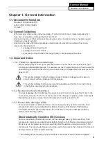
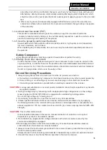
This service information is designed for experienced repair technicians only and is not designed for use by the general
public.
It does not contain warnings or cautions to advise non-technical individuals of potential dangers in attempting to
service a product.
Products powered by electricity should be serviced or repaired only by experienced professional technicians. Any
attempt to service or repair
the product or products dealt with in this service information by anyone else could result in serious injury or death.
SERVICE MANUAL
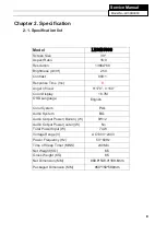
LED TV Model No.
LE39B9000
Main chipset:
TSUMV59XUS
©2013 Qingdao Haier Electronics Co., Ltd.
All rights reserved. Unauthorized copying and
distribution is a violation of law
WARNING
Summary of Contents for LE39B9000
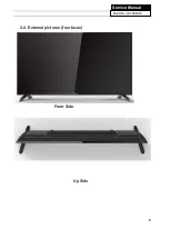
Page 9: ...9 Service Manual Model No LE39B9000 2 2 External pictures four faces Front Side Up Side ...
Page 10: ...10 Service Manual Model No LE39B9000 Right Side Back Side ...
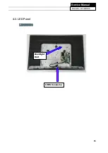
Page 15: ...15 Service Manual Model No LE39B9000 4 3 LED Panel LE39B9000 Backlight Unit LVDS Connector ...
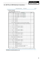
Page 16: ...16 Service Manual Model No LE39B9000 4 4 LED Panel LVDS Interface Connections ...
Page 17: ...17 Service Manual Model No LE39B9000 Chapter 5 Installation Instructions 5 1 Accessories ...
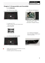
Page 18: ...18 Service Manual Model No LE39B9000 5 2 Base Stand Assembly Instruction ...
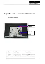
Page 19: ...19 Service Manual Model No LE39B9000 ...
Page 20: ...20 Service Manual Model No LE39B9000 ...
Page 31: ...28 Service Manual Model No LE43B7000 Chapter 9 Trouble shooting 9 1 Trouble shooting ...
Page 32: ...29 Service Manual Model No LE49B7000 ...
Page 33: ...30 Service Manual Model No LE49B7000 ...
Page 34: ...31 Service Manual Model No LE49B7000 ...
Page 35: ...32 Service Manual Model No LE49B7000 ...