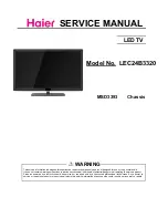


SERVICE MANUAL
LED TV
Chassis
MSD3393
This service information is designed for experienced repair technicians only and is not designed for use by the general public.
It does not contain warnings or cautions to advise non-technical individuals of potential dangers in attempting to service a product.
Products powered by electricity should be serviced or repaired only by experienced professional technicians. Any attempt to
service or repair the product or products dealt with in this service information by anyone else could result in serious injury or death.
WARNING
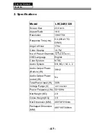
LEC24B3320
Model No.
Summary of Contents for LEC24B3320
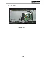
Page 11: ...3 3 LED Panel 10 Service Manual Model No V236BJ1 P01...
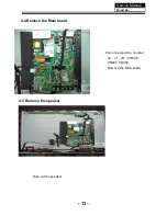
Page 15: ...4 6 Remove the remote control take out the remote controlboard Service Manual Model No 14...
Page 38: ...Service Manual Model No 9 Trouble shooting 9 1 Simple check 38...