background image

MRV II

Aug. 2008

START UP GUIDE

R410A HEAT PUMP 50HZ

SYJS-005-08REV.0

AV08NMVERA

AV10NMVERA

AV12NMVERA

AV14NMVERA

AV16NMVERA

AV18NMVERA

AV20NMVERA

AV22NMVERA

AV24NMVERA

AV26NMVERA

AV28NMVERA

AV28NMVERA

AV30NMVERA

AV32NMVERA

AV34NMVERA

AV36NMVERA

AV38NMVERA

AV40NMVERA

AV42NMVERA

AV44NMVERA

AV46NMVERA

AV48NMVERA

Summary of Contents for MRV II AV48NMVERA

Page 1: ...JS 005 08REV 0 AV08NMVERA AV10NMVERA AV12NMVERA AV14NMVERA AV16NMVERA AV18NMVERA AV20NMVERA AV22NMVERA AV24NMVERA AV26NMVERA AV28NMVERA AV28NMVERA AV30NMVERA AV32NMVERA AV34NMVERA AV36NMVERA AV38NMVERA AV40NMVERA AV42NMVERA AV44NMVERA AV46NMVERA AV48NMVERA ...

Page 2: ...ication address when in central control SW03 on indoor PCB 2 10 Confirm the indoor central control address when in central control SW02 on indoor PCB 2 11 Confirm the indoor group control address when in group control SW01 on indoor PCB 2 12 Confirm the outdoor pipe length switch on outdoor PCB 2 13 Confirm the outdoor capacity over match switch setting on outdoor PCB 2 14 Confirm the outdoor unit...

Page 3: ...pe 182 242 382 482 162 Wall mounted type AS MC AERA 072 092 122 162 182 282 302 382 Console type AF MAERA 072 092 122 Outdoor units Type AV MVERA Model 10HP 10N 12HP 12N 14HP 14N 16HP 16N 18HP 18N 20HP 20N 22HP 22N 24HP 24N 8HP 08N 28HP 28N 30HP 30N 482 092 122 Type AV MVERA Model 34HP 34N 36HP 36N 38HP 38N 40HP 40N 42HP 42N 44HP 44N 46HP 46N 48HP 48N 32HP 32N 722 962 AB MCERA 182 242 282 302 382 ...

Page 4: ...G R U P A d o o 04 AV08NMVERA 1 2 External appearance Outdoor AV16NMVERA AV18 20NMVERA AV22 24 26NMVERA AV28 30 32NMVERA AV34 36NMVERA AV38 40 42NMVERA AV44 46 48NMVERA AV10NMVERA AV14NMVERA AV12NMVERA ...

Page 5: ...IGH ESP DUCT TYPE AD182MHERA AD242MHERA AD282MHERA AD302MHERA AD382MHERA AD482MHERA CONSOLE TYPE AC092MCERA AC122MCERA AC162MCERA AC182MCERA AC242MCERA CONVERTIBLE TYPE AC382MFERA AC482MFERA HRV heat reclaimed ventilation ERV0150ANN ERV0200ANN ERV0260ANN ERV0350ANN ERV0800ANN ERV1000ANN ERV1200ANN ERV1500ANN WALL MOUNTED TYPE AB182MCERA AB242MCERA AB282MCERA AB302MCERA AB382MCERA AB482MCERA 4 WAY ...

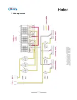
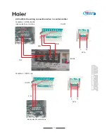
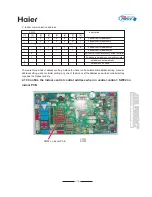
Page 6: ...G R U P A d o o 06 2 Wiring work ...

Page 7: ...the power cables connection of each indoor unit Make sure the position and the connection of live wire L and neutral wire N correct electric control box of indoor except for wall mounted unit electric control box of wall mounted unit ...

Page 8: ...nection of each indoor unit Make sure the position and the connection of P Q cables correct Confirm P cables of all indoors are the same color so Q cables do electric control box of indoor except for wall mounted unit electric control box of wall mounted unit ...

Page 9: ...nect wires B and C 1 2 3 1 2 3 1 2 3 1 2 3 1 2 3 Indoor 16 Indoor 15 Indoor N Indoor 2 Indoor 1 Wired controller Wired controller Wired controller Wired controller Wired controller master unit A B C Wired controller Control wiring of wired controller polar CN22 on indoor PCB Note When in group control type the slave unit can not use individual wired controller ...

Page 10: ... J03 and J06 beside the dip switch old J02 J06 J07 J03 selection item state function description changeover of controller type 0 1 0 1 0 1 0 1 selection of room temp sensor auto restart selection of room temp display set as simple controller set as standard controller use room temp sensor on wired controller not use room temp sensor on wired controller without auto restart with auto restart displa...

Page 11: ...o 11 2 4 Confirm the wiring connection when in central control Condition 1 ICR01 IGU04 indoor electric control box ICR01 IGU04 P Q L N 220 B B B A Condition 2 ICR01 only indoor electric control box ICR01 L N 220 P Q ...

Page 12: ...64 units and every unit can include max 16 indoors but the central controller only displays the master indoor state 00 1 64 01 65 128 10 129 192 11 193 256 position 1 0 ON 1 OFF indoor bus line central bus line 2 master controller slave controller 3 4 For example Select central bus line master central controller control range is 00 so the dip switch is 1 0 0 0 Select indoor bus line master central...

Page 13: ...bles color corresponding 2 7 Confirm the P Q connection and the communication among outdoors A B C connection outdoor electric control box outdoor electric control box Only P Q of master outdoor unit are connected to the indoor unit Pay attention to the color of P Q in accordance Keep the color of A B C accordant ...

Page 14: ...l slave unit Remote control unit Socket jumper CN23 short connected disconnected disconnected CN30 short connected short connected disconnected CN21 blank blank to remote receiver SW08 6 ON ON OFF signal terminal block A B C to B C to A B C not wired controller wired controller to wired controller 2 9 Confirm the indoor communication address when in central control SW03 on indoor PCB SW03 on indoo...

Page 15: ...ess by wired controller 1 Forbidden to set address by wired controller 0 1 set address automatically set address by hand There are three kinds of address setting method for indoor units automatical address setting manual address setting wired controller setting Any one of them can set the address and wired controller setting type has the highest priority 2 10 Confirm the indoor central control add...

Page 16: ...ntral control address 127 __ 1 1 1 1 1 1 1 central control address 128 0 set central control address by wired controller 1 Forbidden to set address by wired controller 2 11 Confirm the indoor group control address when in group control SW01 on indoor PCB SW01 on indoor PCB 1 ON 0 OFF SW01 Description 1 2 3 4 5 6 7 8 0 0 1 1 0 0 1 1 0 0 0 1 0 1 1 1 wired controller address 1 wired controller addres...

Page 17: ...0 0 1 1 0 1 1 SW4 2 description medium piping length long piping length cooling suction pressure 7 51kgf cm 2 heating discharging pressure 30 0kgf cm 2 short piping length cooling suction pressure 8 53kgf cm 2 heating discharging pressure 26 0kgf cm 2 1 ON 0 OFF SW4 1 SW4 2 2 13 Confirm the outdoor capacity over match switch setting on outdoor PCB 0 1 SW4 4 over match capacity setting allowable fo...

Page 18: ... 0 0 0 1 1 1 1 0 0 1 1 0 0 1 1 0 1 0 1 0 1 0 1 SW4 6 7 8 used to set outdoor unit No and outdoor unit No lock 1 ON 0 OFF SW4 6 7 8 SW4 5 2 15 Confirm the outdoor units searching when multi units in combination SW4 5 0 1 searching outdoor after being electrified begin to search outdoor stop searching outdoor and lock the outdoor quantity ...

Page 19: ...G R U P A d o o 19 2 16 Confirm the outdoor capacity SW2 1 SW2 2 SW2 3 8HP 10HP 12HP 14HP 16HP 20HP 22HP 0 0 0 0 1 1 1 1 0 0 1 1 0 0 1 1 0 1 0 1 0 1 0 1 SW2 8 bit dip switch outdoor capacity 18HP ...

Page 20: ...s 1 5 display indoor failure code no failure display 0 LED3 LED4 indoor available display 1111 indoor unavailable display function indoor communication checking indoor abnormal indoor capacity air inlet temp indoor gas pipe temp indoor EEV open angle SW11 3 4 5 6 7 8 9 SW9 0 1 2 3 address 1 16 17 32 33 48 49 64 indoor liquid pipe temp LED2 LED3 LED4 display air inelt temp 2 degree displays 02 10 1...

Page 21: ...outdoor valve output indication LED1 1 open SV7 0 close LED2 1 open SV6 0 close LED3 1 open SV5 0 close LED4 1 open SV4 0 close outdoor PMV1 open angle outdoor PMV2 open angle 0 2000 steps 0 480 steps outdoor valve output indication LED1 1 open SV8 0 close LED2 1 open SV9 0 close LED3 1 open SV10 0 close LED4 1 open SV11 0 close outdoor valve and heater output indication LED1 1 open SV12 0 close L...

Page 22: ...for 40HP e g 4 outdoors excluding inverter outdoor e g 64 indoors depend on if thermostat is ON running indoor QTY outdoor QTY in one system 2 17 3 Inverter unit information center display parameters of the whole system 407 stands for R407C 410 stands for R410A indoor QTY in one system indoor QTY whose operation modes are as the same as that of outdoor e g 13 indoors SW9 SW10 SW11 function descrip...

Page 23: ...ter it is close or press STOP EEV1 will close and display 7 2 6 fan motor runs from high speed to low speed press START to enter 9 high speed press again to enter 7 and so on Press STOP fan motor stops and display 8 2 6 6 9 2 press SW8 for 2 seconds to start and press SW7 for 2 minutes to stop all indoors will start up as cooling mode ignore air inlet temp EEV open angle is at the standard positio...

Page 24: ...her is automatical control Outdoor frequency will not change according to indoor capacity outdoor compulsory heating mode in rated condition press START for 2 seconds display HEAT to enter heating mode inverter control begins Press STOP for 2 seconds display Outdoor rated operation frequency is 80Hz the other is automatical control Outdoor frequency will not change according to indoor capacity WAR...

Page 25: ...ording to the temp difference between the set temp and the room temp C Dry operation room temp set temp 2 indoor operation is identical with the cooling operation and send the cooling mode to outdoor room temp set temp 2 indoor will send the dry signal to outdoor and indoor fan motor will run at low speed compulsorily when compressor is running when room temp 16 indoor stops and sends stop signal ...

Page 26: ...ce arriving the requested time set by SW07 6 indoor will send filter cleaning signal to wired controller when indoor recieves the filter reset signal from wired controller if the time exceeds the requested time the filter will reset d Compulsory defrosting after indoor receives the compulsory defrosting signal from wired controller it will send compulsory defrosting signal to outdoor contineously ...

Page 27: ...FF œ SWING œ OFF E TEMP In RECOVERY mode there is no set temp after being electrified again the displayed temp is the latest temp Every time press TEMP button SET icon will display and the set temp will increase decrease 1 degree keep pressing it within 5 seconds the set temp will change at 1 degree 0 5 second 5 seconds later the set temp will change at 21 degrees second if no pressing within 10 s...

Page 28: ...r will be cleared e Query indoor performance state In normal state press both buttons of CHECK and FILTER for 5 seconds in the set temperature region in the screen XX will display XX is indoor number which can be selected by pressing TEMP In the timer region in the screen YZZZ will display in which Y stands for data type ZZZ stands for the corresponding data which can be selected by pressing CLOCK...

Page 29: ... turns form orange color to green color oxygen pump generator starts up to apply oxygen to indoor Press the button again the sign disappeared after all health function of the indoor unit being fully canceled oxygen pump stopped About Health functon only has oxygen pump fancton There is NEGATIVE ION function on the WALL MOUNTED type and CABINET type indoor units the detailed information of this fun...

Page 30: ...ODE Button Used to select Code A or B this manual is for code B 14 HIGH SO Button Used to select HIGH or SOFT operation 11 LIGHT Button Used to light the control panel only for cabinet unit 12 LOCK Button Used to lock operation button and LCD display contents by pressing this button other buttons comes out of function and lock state display appears if you press it again lock state will be no more ...

Page 31: ... are correctly placed in the compartment as required for positive and negative terminals Replacing the battery compartment lid The battery compartment lid is reinstalled in the reverse sequence Display review Press the button to see if batteries are properly fitted If no display appears refit the batteries Note It is recommended that the batteries be removed from the compartment if the remote cont...

Page 32: ...fan speed COOL operation starts when room temp is higher than temp setting Every time the button is pressed temp setting increases 1degree If button is kept depressed temp setting will increase quickly Every time the button is pressed temp setting decreases 1degree If button is kept depressed temp setting will decrease quickly Set proper temperature A U T O LOW MID HIGH AUTO FRESH HIGH SO TIMER SE...

Page 33: ...onfirming After time setting press SET button to confirm time Timer ON OFF Function After replacing batteries or if apower failure occurs TIMER setting must be reset Remote controller has memory function When you use TIMER mode next time just press SET button after mode selection if timer setting is the same as the previous one Press time button Every time the button is pressed time increases an h...

Page 34: ...e working mode Press the Fresh air button of the remote controller the LCD displays and the unit begins continuous fresh air operation press the button again the in flashes and begin automatic fresh air operation press the button for the third time to cancel fresh air function Continuous fresh air operation That is to say if there is no intervention the fresh air operation will continuously run an...

Page 35: ...essure is more than 2 1MPa outdoor motor will increase one class at interval of 60 seconds if pressure is over 2 6MPa outdoor motor will rise up to class 7 If pressure is less than 1 9MPa for 60 seconds fan motor will decrease one class If less than 1 8MPa for 60 seconds fan motor will stop b In heating mode Motor control in startup procedure before 4 way valve reverses in heating mode outdoor mot...

Page 36: ...In defrosting operation a 4 way valve OFF b outdoor motor OFF c anti cold air control of indoor motor OFF d outdoor EEV OFF Quit defrosting Any of the below conditions can be met the unit will quit defrosting a After defrosting begins 10 minutes later defrosting is over b Detect the defrosting condition of outdoor heat exchanger by TE all the temperatures at the defrosting point are over 10 degree...

Page 37: ...mperature 9 Oil return quit condition After oil return the system will enter refrigerant elimination 3 Oil return procedure in heating mode 1 After the compressor frequency enters 90Hz in the course if the discharging pressure or discharging temperature is too high the reducing frequency protection will be prior 2 The standby outdoor will start up and its frequency is 90Hz 3 Outdoor EEV will be fu...

Page 38: ...f factory ON OFF SW01 1 2 3 4 5 6 7 8 ON OFF SW02 1 2 3 4 5 6 7 8 ON OFF SW03 1 2 3 4 5 6 7 8 SW08 5 Status of SW08 5 ON OFF Controlling Method Room card available unavailable ON OFF SW08 6 Status of SW08 6 Controlling Method Wired control include one control to multiple units two controls to one unit and one control to one unit Remote control 5 Dip switch setting when out of factory OR after 5 mi...

Page 39: ...door unit 2 To other outdoor unit Communication cable Shielded wire Power cable C B A Q P 1 L 2 N 2 N 1 L P Q A B C L N To other indoor unit To wired controller A B C To outdoor unit P Q To power cable Communication cable Shielded wire Power cable Wiring of indoor units for example Wiring of outdoor units for example 6 Wiring of indoor and outdoor ...

Page 40: ...G R U P A d o o 40 ...

Reviews: