background image

ENGLISH  

No. 0150563873  B
31-5000755   Rev. 0   06-23   

GEA

Installation Instructions 

Installation Manuel

Instrucciones de instalación
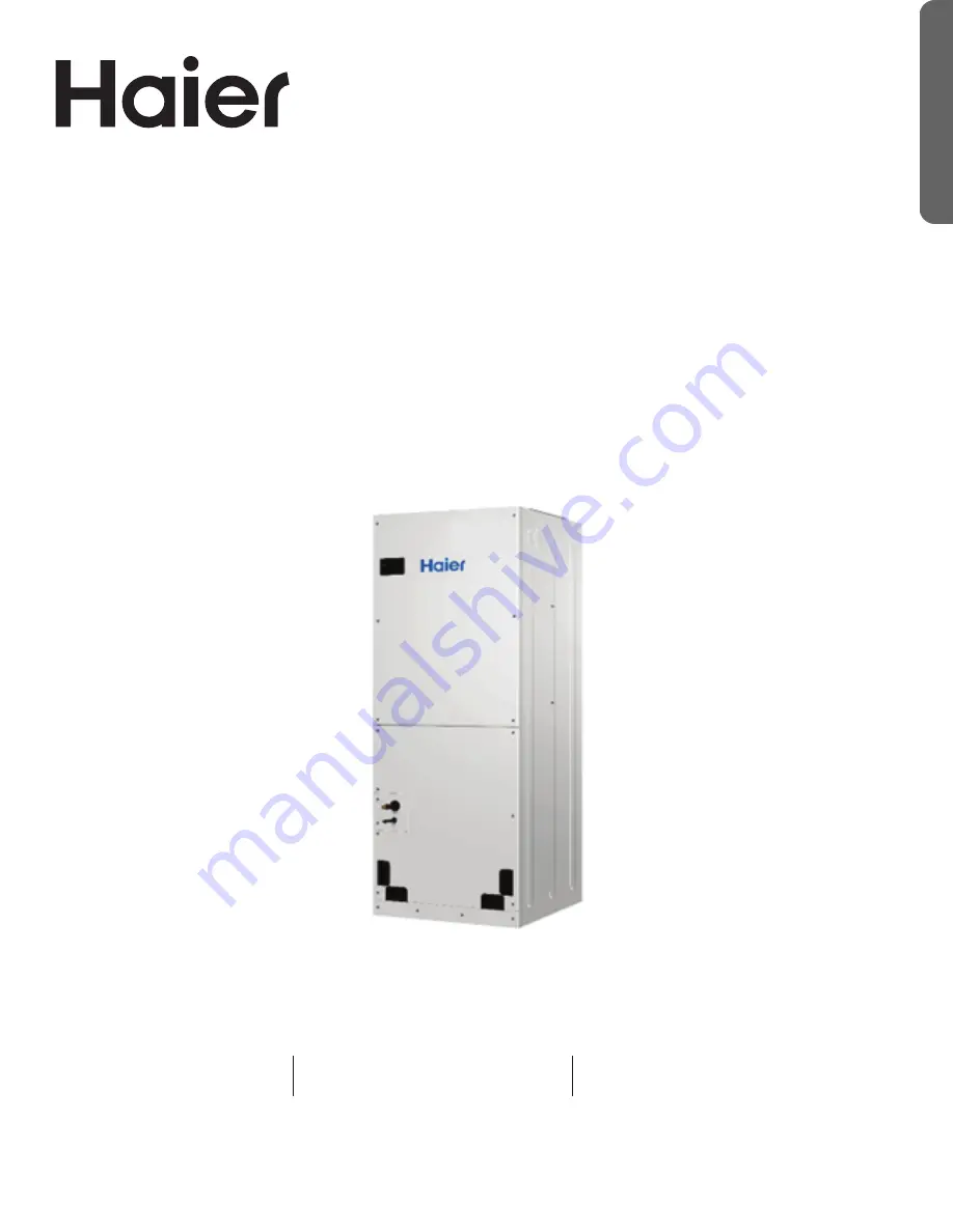
MVAX009ME2AA1

MVAX012ME2AA1

MVAX018ME2AA1

MVAX024ME2AA1

MVAX030ME2AA1

MVAX036ME2AA1

MVAX042ME2AA1

MVAX048ME2AA1

MVAX054ME2AA1

MVAX060ME2AA1

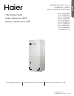
Design may vary by model number.

L’aspect peut varier selon le numéro de modèle.

El diseño puede variar según el número de model.

MRV Indoor Unit

Unité intérieure MRV

Unidad Interior con MRV

Summary of Contents for MVAX009ME2AA1

Page 1: ...MVAX009ME2AA1 MVAX012ME2AA1 MVAX018ME2AA1 MVAX024ME2AA1 MVAX030ME2AA1 MVAX036ME2AA1 MVAX042ME2AA1 MVAX048ME2AA1 MVAX054ME2AA1 MVAX060ME2AA1 Design may vary by model number L aspect peut varier selon l...

Page 2: ......

Page 3: ...Serial number _______________________________________ Date of purchase To register your new Haier Duct Free system go to Haierductless com product registration and input the model serial number inform...

Page 4: ...e control system Keep the equipment and its cord out of reach of children Product Features 1 Suspended indoor unit installation saves space 2 Automatic display of error and fault codes Please refer to...

Page 5: ...appliance by a person responsible for their safety Children should be supervised to ensure that they do not play with the appliance To avoid danger of suffocation keep the plastic bag or thin film use...

Page 6: ...ldren should be supervised to ensure that they do not play on or near the equipment Keep the appliance and its power supply wiring out of reach of children This equipment is not intended to be operate...

Page 7: ...rmance Peak pressure of R410A is much higher than R22 Use copper tubing with adequate wall thickness To prevent breaking of the pipe avoid sharp bends Bend the pipe with a radius of curvature of 4 in...

Page 8: ...Btu h 42000 48000 Heating Btu h 46000 54000 Electrical Power supply V Ph Hz 208 230 1 60 208 230 1 60 MCA A MOP A 15 15 ESP in W G 0 3 0 5 0 9 0 3 0 5 0 9 54k 60k Capacity Cooling Btu h 54000 60000 H...

Page 9: ...ECIFICATIONS Unit Dimensions Model Width Depth Height A B 17 1 2 in 445mm 21 in 533mm 47in 1194mm 11 11 16in 297mm 16 1 2 in 419mm MVAX042 048ME2AA1 21 in 533mm 53in 1346mm 20 in 506mm MVAX054 060ME2A...

Page 10: ...onal injury and property damage Select the following places to install indoor units 1 Where there is enough room for the unit above the ceiling 2 Where the drainpipes can be well positioned 3 Where th...

Page 11: ...ncealed area and not accessible to the general public or animals If air handler is installed in the vertical position make sure there is enough room around the unit for service and maintenance The uni...

Page 12: ...8 41 2 3 MODEL DOWNFLOW FRONT LEFT RIGHT BEHIND BELOW ABOVE MVAX009 036ME2AA1 24 19 2 3 34 5 7 21 2 5 MVAX042 048ME2AA1 38 1 6 24 1 7 MVAX054 060ME2AA1 41 2 3 25 5 8 MODEL HORIZONTAL RIGHT FLOW FRONT...

Page 13: ...ontal Right Flow Installation The drain pan needs to be moved from the left side of the coil to catch and drain condensate 1 Detach TC1 and TC2 thermistors ring temperature sensor and thermostat from...

Page 14: ...rmistor and the temperature sensor are on the front of the coil and the second thermistor on the left side 2 Slide coil assembly and both drain pans out of the air handler The side water tray should b...

Page 15: ...ew metal side panels onto coil one on each side 6 Unscrew internal electrical box Loosen the black waterproof cable plug and adjust the harness to allow for more slack in the wires This is required in...

Page 16: ...ould be on the wires There is a lip on the back edge of the metal shelf that aligns with the slot at the bottom of the front of the electrical box 8 Optional If needed install electric heater followin...

Page 17: ...rnal electrical box Loosen the black waterproof cable plug and adjust the harness to allow for more slack in the wires This is required in order to take tension off the cables when the electrical box...

Page 18: ...allation 13 Undo white cable ties along the side of the unit to make room for coil reinstallation 14 Slide the coil back into the unit along the side rails in the orientation shown below Only include...

Page 19: ...ure sensor should be inserted into the upper hole of the evaporator cover with a wire clamp The hole in the front of the triangular plate where the temperature sensor was originally located may remain...

Page 20: ...ve the upper access panel from air handler Remove cover plate from air handler Slide the heater kit into the slot and secure element plate with previously removed screws Insert power leads into the ci...

Page 21: ...other is set to be the auxiliary wired control The main wired control and indoor units and the main and auxiliary line controls are connected via three lines with polarity Note For DC motor low ESP du...

Page 22: ...4 060ME2AA Piping Size in mm Gas pipe 3 8 9 52 5 8 15 88 5 8 15 88 5 8 15 88 Liquid pipe 1 4 6 35 3 8 9 52 3 8 9 52 3 8 9 52 Piping Material R 410a rated seamless copper tubing Connecting Procedures o...

Page 23: ...ill prevent odors from entering indoors or corrupting the unit DO NOT connect the condensate drain pipe into the rain pipe This will prevent rain water from pouring in and causing property loss or per...

Page 24: ...or to servicing any component in the system Wire Connections 1 Connecting ring terminals The method of using circular terminal is shown in the figure Take off the screw connect it to the terminal afte...

Page 25: ......

Page 26: ...er wire shall not be more than 820ft 250m P Q P Q A B C P Q A B C P Q A B C A B C Outdoor Indoor 1 Indoor 4 Indoor 7 Indoor 2 Indoor 5 Indoor 8 Indoor 3 Indoor 6 Indoor 9 P Q A B C P Q A B C P Q A B C...

Page 27: ...s 1 2 3 4 Address of wire controlled indoor unit group address SW03_1 SW03_2 SW03_3 SW03_4 Address of wire controlled indoor unit group address 0 0 0 0 0 wire controlled main unit default 0 0 0 1 1 wi...

Page 28: ...1 0 0 0 0 1 0 2 66 1 1 1 1 1 1 1 63 127 Note Set the address by code when connecting the centralized controller or gateway or charge system Address of centralized controller communication address 0 or...

Page 29: ...Sw5 On Old protocol Off Off Self adaption Sw6 On reserved Off Off reserved Sw7 On Model with Up Down and Left Right swing Off Off Model with Up Down swing Sw8 On Fresh Air unit Off Off General unit Fo...

Page 30: ...ower supply can the operator clean the air conditioner otherwise there is a risk of electric shock or injury Make sure to use a stable platform while cleaning or servicing the equipment Do not flush t...

Page 31: ...ndicator flashes Waiting indicator Displayed when the control is set it to the cooing or heating mode and the current mode of operation is opposite to the requested setting Idle indoor unit still has...

Page 32: ...s fastened Check if the refrigerant and condensation lines are insulated Check if the water is drained to the outside Check if the indoor units are positioned RUN TEST Equipment installers should test...

Page 33: ...r TC1 03 3 Fault of indoor unit pipe temp sensor TC2 04 4 Fault of indoor unit dual heat source temp sensor 05 5 Fault of indoor unit EEPROM 06 6 Fault of communication between indoor outdoor units 07...

Page 34: ...34 31 5000755 Rev 0 ENGLISH NOTES...

Page 35: ...installer s invoice If the installation date cannot be verified then the Date of Purchase will be sixty 60 days after the manufacture date as determined by the Product s serial number You should keep...

Page 36: ...s the District of Columbia and Canada This warranty it provided by GE Appliances a Haier company Louisville KY 40225 The Product is defined as Haier brand Ductless Split Units The Product contains 2 s...

Reviews: