
31-5000755 Rev. 0
7
ENGLISH
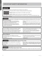
IMPORTANT SAFETY INFORMATION
READ AND SAVE THESE INSTRUCTIONS
CAUTION
• It is highly recommended that you do not open or close
the stop valves when the outdoor temperature is below
-5°F(-21°C) as this may cause refrigerant leakage.
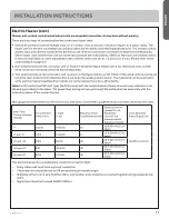
• Make sure power is turned on for at least 12 hours
after periods of being powered down in an 32 °F (0°C)
environment or lower.
• Do not touch the fins of the coil. Touching the coil fins
could result in damage to the fins or personal injury such
as skin rupture.
• Ensure the power circuit capacity is adequate for all loads
connected to the electrical service panel. Increase the
conductor and panel capacity if the total electrical loads
exceed the power source capacity.
• Contact the power utility if the power provided is below
equipment rating plate requirements.
• Be sure to install a breaker of the specified capacity.
• Regulation of cables and breaker differs from each
locality, refer in accordance with local rules.
• Do not use existing refrigerant lines.
• Use refrigerant tubing that is clean and free of any
contamination which may cause damage to the system
including sulfur, copper oxide, dust, metal chips, powder,
oil or water.
• Avoid brazing lines together. Use a continuous length of
copper tubing as oxides formed during improper brazing
techniques can damage the equipment.
• Do not use copper pipes that have a collapsed, deformed,
or discolored portion (especially on the interior surface).
• Otherwise, the expansion valve or capillary tube may
become blocked with contaminants.
• Improper line sizing will degrade performance. Peak
pressure of R410A is much higher than R22. Use copper
tubing with adequate wall thickness.
• To prevent breaking of the pipe, avoid sharp bends. Bend
the pipe with a radius of curvature of 4 in. (100 mm ) or
more.
• If the pipe is bent repeatedly at the same place, it will
break.
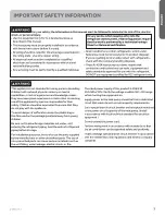
BEFORE YOU BEGIN
Read these instructions completely and carefully.
• IMPORTANT
–
Save these instructions for local
inspector’s use.
• IMPORTANT
–
Observe all governing codes and
ordinances.
• Note to installer
– Be sure to leave these instructions
with the Consumer.
• Note to consumer
– Keep these instructions for future
reference.
• Skill level
– A licensed certified technician (to handle
refrigerant R-410A, recovery, etc) and a qualified
electrician are required for installation and service of this
split heat pump system.
• Proper installation is the responsibility of the installer.
• Product failure due to improper installation is not
covered under the limited warranty.
• For personal safety, this system must be properly
grounded.
• Protective devices (fuses or circuit breakers) acceptable
for installation are specified on the nameplate of each
unit.
• Make sure to avoid wiring or plumbing inside the wall
when installing.
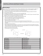
CAUTION
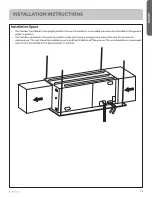
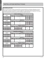
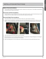
• The dimensions of the space necessary for correct
installation of the appliance including the minimum
permissible distances to adjacent structures is in the
installation part.
• The minimum CLEARANCE from the appliance to
combustible surfaces is in the installation part.
• Details of supplementary heating elements is in the
installation part.
• The maximum operating pressure is considered when
connecting to any outdoor units
• These units must only be connected to other units that
have been confirmed as complying to
• UL 60335-1
• UL 60335-2-40
• CSA C22.2 #60335-1
• CSA C22.2 #60335-2-40


