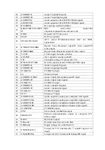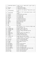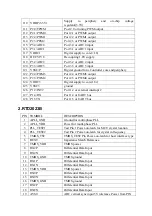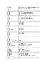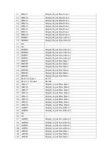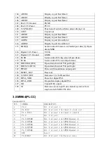
110 VDDP(3.3V)
Supply to periphery and on-chip voltage
regulator(3.3V)
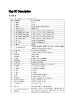
111 P2.0/TPWM
Poet 2.0 or tuning PWM output
112 P2.1/PWM0
Port 2.1 or PWM0 output
113 P2.2/PWM1
Port 2.2 or PWM1 output
114 P2.3/PEM2
Port 2.3 or PWM2 output
115 P3.0/ADC0
Port 3.0 or ADC0 input
116 P3.1/ADC1
Port 3.1 or ADC1 input
117 VDDC1
Digital supply to core(+1.8)
118 DECV1V8
Decoupling
1.8V
supply
119 P3.2/ADC2
Port 3.2 or ADC2 input
120 P3.3/ADC3
Port 3.3 or ADC3 input
121 VSSC/P
Digital ground for u-Controller core and periphery
122 P2.4/PWM3
Port 2.4 or PWM3 output
123 P2.5/PWM4
Port 2.5 or PWM4 output
124 VDDC3
Digital supply to core(1.8v)
125 VSSC3
ground
126 P1.2/INT2
Port 1.2 or external interrupt 2
127 P1.4/RX
Port 1.4 or UART bus
128 P1.5TX
Port 1.5 or UART bus
2.RTD2023B
PIN SYMBOL
DESCRIPTION
1
APLL_GND
Ground for multi-phase PLL
2
APLL_VDD
Power for multi-phase PLL
3
PLL_TEST1
Test Pin 1 Power-on-latch for MCU crystal location
4
PLL_TEST2
Test Pin 2 Power-on-latch for crystal in frequency
5
TMDS_TST
TMDS_TEST Pin Power-on-latch for host interface type
6
REXT
Impedance Match Reference.
7
TMDS_VDD
TMDS power
8 RX2P
Differential
Data
Input
9 RX2N
Differential
Data
Input
10 TMDS_GND
TMDS ground
11 RX1P
Differential
Data
Input
12 RX1N
Differential
Data
Input
13 TMDS_VDD
TMDS power
14 RX0P
Differential
Data
Input
15 RX0N
Differential
Data
Input
16 TMDS_GND
TMDS ground
17 RXCP
Differential
Data
Input
18 RXCN
Differential
Data
Input
19
AVS0
ADC vertical sync input 5V tolerance Power from PIN
Summary of Contents for NS-CL19C
Page 1: ...NS CL19C ...
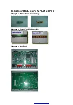
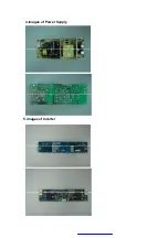
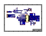
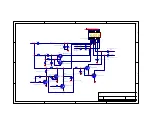
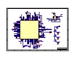
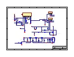
Page 8: ...4 images of Power Supply 5 images of Inverter ...


