background image

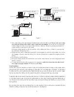
1.Tubing should be cut square. Make sure it is round and free of burrs at the connecting ends.
    Clean the tubing to prevent contamination from entering the system.
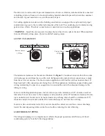
2.Make sure that both refrigerant stop valves at the outdoor unit are closed.
3.Push the tubing into the fitting until it stops. This prevents flux from getting into the system.
4.Remove the cap and Schrader valve core from the service port to protect the valve seals.
5.Wrap a wet rag around the valve stub before brazing.
6.Braze the joints of interconnecting tubing. Flow dry nitrogen into the shutoff valve port
   and through the tubing while brazing.
7.After brazing quench with a wet rag to cool the joint. Reinstall the Schrader core in the valve,
    if removed for brazing.
8.Pressurize the lines to 150 psi maximum with dry nitrogen. Check for leaks at all joints with
   liquid detergent. If a leak is found, repair it after removing the nitrogen. Repeat the process
   and re-ckeck.
9.Do not purge the lines with refrigerant. Evacuate the lines and indoor coil.

Evacuation

All new installations must be evacuated to a deep vacuum in order that all noncondensible gases
and moisture are removed prior to charging the system. Air in a system causes high condensing
pressure, which increases power consumption and reduces performance. The presence of moisture
in a system can render it inoperable in a very short time. Proper evacuation assures a dry, uncontaminated
system. Here is the recommended evacuation procedure:

1.Connect vacuum pump to both liquid and suction valve service ports.
2.Evacuate the interconnecting tubing and indoor coil to 500 microns or less for a minimum
   of 30 minutes. Close the valve to the vacuum pump and wait 15 minutes. Vacuum should
   not rise above 800 microns. If unable to obtain 500 microns, or vacuum rises above 800
   microns over 15 minutes period, discontinue evacuation, pressurize and check for leaks.
   Repair any leaks found and repeat the step 2.
3.Close valve to the vacuum pump and stop pump.
4.When sure of a tight, well evacuated system, charge with refrigerant.

Charging the System

(For systems with capillary tube or fixed orifice metering device)

Before checking the system charge, make sure that the outdoor unit and indoor coil must be an
approved match per the unit specification. The indoor conditions should be within 2 F of the desired
comfort conditions.

! WARNING

 - 

Do not vent refrigerant to the atmosphere

! It is a violation of federal law to do

so. If the refrigerant needs to be removed from a system to correct the charge inside, always use a
recovery or recycling device.

! WARNING

 -  To prevent personal injury, 

wear safety glasses and gloves when handling

refrigerant

.

7

Summary of Contents for V1124C2H

Page 1: ...1 5 to 5 Tons Models V1118C2H V1124C2H V1130C2H V1136C2H Installation Operation Manual Central Air Conditioner The information contained in this booklet is subject to change without notice V1142C2H V1...

Page 2: ...service personnel for proper installation adjustment and operation of this unit Read these instructions thoroughly before attempting installation or operation Failure to follow these instructions may...

Page 3: ...spection 5 Equipment Protection From Environment 6 Installation 6 1 General 6 2 Unit clearances 6 3 Refrigerant piping 6 4 Electrical wiring 7 System Startup 8 Operation 9 Miscellaneous 9 1 Replacemen...

Page 4: ...Carefully read this manual and any instructions packaged with separate equipment required to make up the system prior to installation Give this manual to the owner and explain its provisions The owne...

Page 5: ...770 770 705 770 770 805 23 23 31 1 2 585 585 805 23 23 27 3 4 585 585 705 23 23 24 585 585 605 23 23 24 585 585 605 23 23 24 585 585 605 23 23 24 585 585 605 31 5 8 31 5 8 30 5 8 31 5 8 31 5 8 34 5 8...

Page 6: ...cal power to the unit before servicing Disconnect power to both the indoor and outdoor units NOTE There may be more than one electrical disconnect switch Failure to shut off power can cause electrical...

Page 7: ...are made from the service access area The most common application will find the unit best located about 10 from back wall with connection side facing the wall This application minimizes exposed tubing...

Page 8: ...t kink or twist the tubing Refrigerant piping should not be installed in a cement slab as this limits access to the refrigerant should a leak be suspected To ensure good oil return to the compressor i...

Page 9: ...are charged with refrigerant Condensing unit liquid and suction valves are closed to contain the charge within the unit Do not force the valve stem against the retaining ring If the valve stem is back...

Page 10: ...ch increases power consumption and reduces performance The presence of moisture in a system can render it inoperable in a very short time Proper evacuation assures a dry uncontaminated system Here is...

Page 11: ...o not connect many devices to one AC outlet It could cause a fire or an electric shock due to defective contact defective insulation exceeding the permissible current etc Perform electrical work accor...

Page 12: ...for disconnecting power service to the unit The condensing unit control wiring requires a 24 Volt minimum 25 VA service from the indoor transformer as shown on the wiring diagram 7 SYSTEM STARTUP 1 Tu...

Page 13: ...it can take up to 2 hours for this overload to reset Make sure overload has had time to reset before condemning the compressor 9 MISCELLANEOUS 9 1 Replacement Parts Contact your local distributor for...

Page 14: ...y tubes Replace coil assembly Low vapor cool Low evaporator airflow Increase blower speed or reduce restriction replace air filter compressor iced Operating below 65 F outdoors Add low ambient kit eva...

Page 15: ...8 COM BL R TRAN COM 230 7 BL 5 3 RD NO GR 8 6 4 OFM M BK BR 6 S R BR L1 L2 GND 60Hz 1PH 208 230V WH BK BCR 1 BK 2 RD BRK BK L2 RD RD FL L1 BK FL USE COPPER CONDUCTORS ONLY WARNING CABINET MUST BE PERM...

Page 16: ...VOLTAGE FACTORY STANDARD FIELD INSTALLED OPTIONAL L1 L3 L1 L2 L3 1 Confirm system selection Optional components may be field or factory installed 2 If LPS and or HPS and or VTS not installed or remove...

Page 17: ...Made in P R C...

Reviews: