background image

8.OPERATION

Most single phase units are operated without start relay or start capacitor. Such systems should
be off for a minimum of 5 minutes before restarting to allow equalization of pressures. The
thermostat should not be moved to cycle unit without waiting 5 minutes. To do so may cause
the compressor to stop on an automatic open overload device or blow a fuse. Poor electrical
service can cause nuisance tripping in overloads or blow fuses.

The compressor has an internal overload protector. Under some conditions, it can take up to 2
hours for this overload to reset. Make sure overload has had time to reset before condemning
the compressor.

9.MISCELLANEOUS

9.1.

Replacement Parts

Contact your local distributor for a complete parts list.
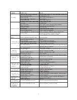
9.2.

Troubleshooting Guide

Refer to the troubleshooting guide (

Table 5

) included in this manual.
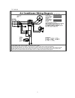
9.3.

Wiring Diagram

Refer to the appropriate wiring diagram included in this manual.(P12,P13)

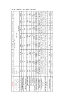
Table 5:Troubleshooting Guide

! WARNING

 - Disconnect all electrical power to the unit before servicing. Disconnect power to

both the indoor and outdoor units. NOTE: There may be more than one electrical disconnect switch.
Failure to shut off power can cause electrical shock resulting in personal injury or death.

10

Summary of Contents for V1124C2H

Page 1: ...1 5 to 5 Tons Models V1118C2H V1124C2H V1130C2H V1136C2H Installation Operation Manual Central Air Conditioner The information contained in this booklet is subject to change without notice V1142C2H V1...

Page 2: ...service personnel for proper installation adjustment and operation of this unit Read these instructions thoroughly before attempting installation or operation Failure to follow these instructions may...

Page 3: ...spection 5 Equipment Protection From Environment 6 Installation 6 1 General 6 2 Unit clearances 6 3 Refrigerant piping 6 4 Electrical wiring 7 System Startup 8 Operation 9 Miscellaneous 9 1 Replacemen...

Page 4: ...Carefully read this manual and any instructions packaged with separate equipment required to make up the system prior to installation Give this manual to the owner and explain its provisions The owne...

Page 5: ...770 770 705 770 770 805 23 23 31 1 2 585 585 805 23 23 27 3 4 585 585 705 23 23 24 585 585 605 23 23 24 585 585 605 23 23 24 585 585 605 23 23 24 585 585 605 31 5 8 31 5 8 30 5 8 31 5 8 31 5 8 34 5 8...

Page 6: ...cal power to the unit before servicing Disconnect power to both the indoor and outdoor units NOTE There may be more than one electrical disconnect switch Failure to shut off power can cause electrical...

Page 7: ...are made from the service access area The most common application will find the unit best located about 10 from back wall with connection side facing the wall This application minimizes exposed tubing...

Page 8: ...t kink or twist the tubing Refrigerant piping should not be installed in a cement slab as this limits access to the refrigerant should a leak be suspected To ensure good oil return to the compressor i...

Page 9: ...are charged with refrigerant Condensing unit liquid and suction valves are closed to contain the charge within the unit Do not force the valve stem against the retaining ring If the valve stem is back...

Page 10: ...ch increases power consumption and reduces performance The presence of moisture in a system can render it inoperable in a very short time Proper evacuation assures a dry uncontaminated system Here is...

Page 11: ...o not connect many devices to one AC outlet It could cause a fire or an electric shock due to defective contact defective insulation exceeding the permissible current etc Perform electrical work accor...

Page 12: ...for disconnecting power service to the unit The condensing unit control wiring requires a 24 Volt minimum 25 VA service from the indoor transformer as shown on the wiring diagram 7 SYSTEM STARTUP 1 Tu...

Page 13: ...it can take up to 2 hours for this overload to reset Make sure overload has had time to reset before condemning the compressor 9 MISCELLANEOUS 9 1 Replacement Parts Contact your local distributor for...

Page 14: ...y tubes Replace coil assembly Low vapor cool Low evaporator airflow Increase blower speed or reduce restriction replace air filter compressor iced Operating below 65 F outdoors Add low ambient kit eva...

Page 15: ...8 COM BL R TRAN COM 230 7 BL 5 3 RD NO GR 8 6 4 OFM M BK BR 6 S R BR L1 L2 GND 60Hz 1PH 208 230V WH BK BCR 1 BK 2 RD BRK BK L2 RD RD FL L1 BK FL USE COPPER CONDUCTORS ONLY WARNING CABINET MUST BE PERM...

Page 16: ...VOLTAGE FACTORY STANDARD FIELD INSTALLED OPTIONAL L1 L3 L1 L2 L3 1 Confirm system selection Optional components may be field or factory installed 2 If LPS and or HPS and or VTS not installed or remove...

Page 17: ...Made in P R C...

Reviews: